Image decoding apparatus, image decoding method, and computer-readable recording medium

a decoding apparatus and image technology, applied in the direction of redundant data error correction, coding, code conversion, etc., can solve the problems of affecting the efficiency of parallelism during normal time, the inability to expect the receiving terminal to always receive stream data, and the inability to achieve high-frequency mixing of stream data errors

Inactive Publication Date: 2010-09-23
KK TOSHIBA
View PDF6 Cites 7 Cited by
  • Summary
  • Abstract
  • Description
  • Claims
  • Application Information

AI Technical Summary

Problems solved by technology

Therefore, it cannot be expected that the receiving terminal always receives stream data in a stable radio wave environment.
In particular, in an environment in which the receiving terminal is hidden behind a building or the like, errors are highly frequently mixed in the stream data.
However, because err

Method used


Image

  • Image decoding apparatus, image decoding method, and computer-readable recording medium
  • Image decoding apparatus, image decoding method, and computer-readable recording medium
  • Image decoding apparatus, image decoding method, and computer-readable recording medium

Examples


Embodiment Construction

[0019]Exemplary embodiments of the present invention are explained in detail below with reference to the accompanying drawings. The present invention is not limited by the embodiments. Components in the embodiments explained below include components that can be easily conceived by those skilled in the art or components substantially the same as the components. In the embodiments, an H.264 / AVC decoder is explained as an example of an image decoding apparatus.

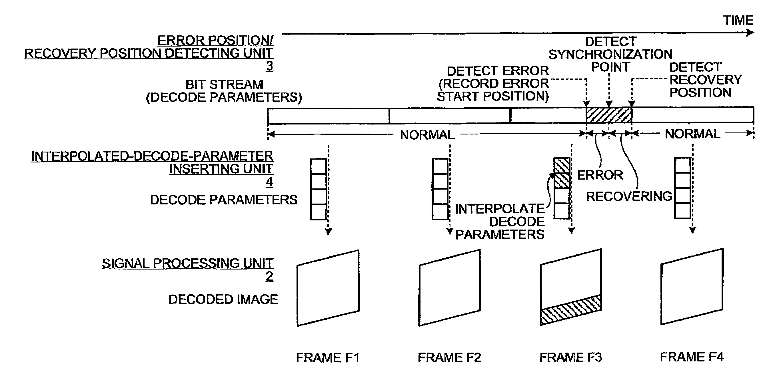
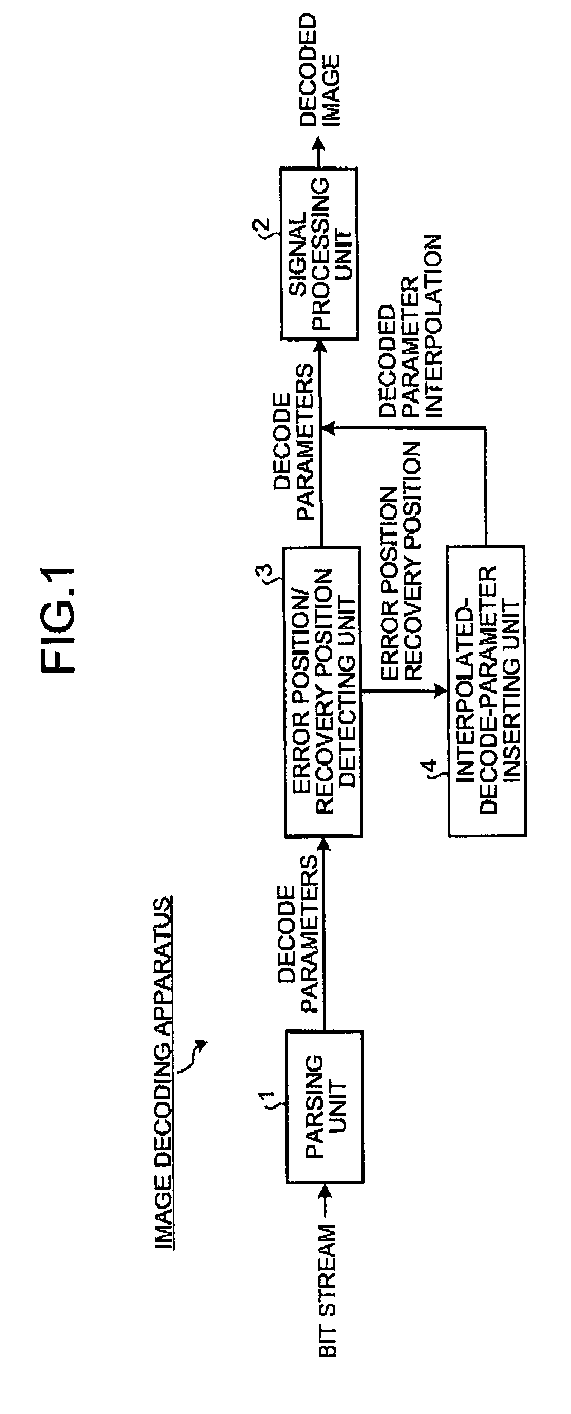
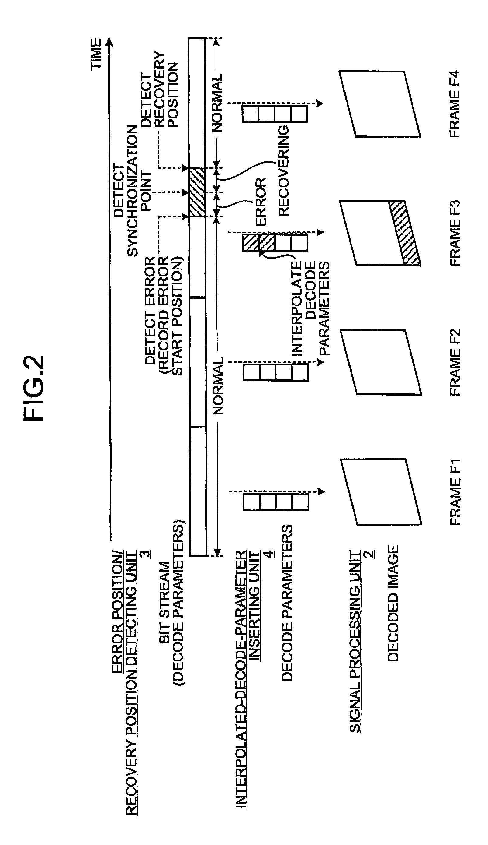
[0020]FIG. 1 is a diagram of a schematic configuration example of an image decoding apparatus according to an embodiment of the present invention. The image decoding apparatus according to this embodiment includes, as shown in FIG. 1, a parsing unit 1 and a signal processing unit 2. The image decoding apparatus further includes an error position / recovery position detecting unit 3 and an interpolated-decode-parameter inserting unit 4 between the parsing unit 1 and the signal processing unit 2.

[0021]The parsing unit 1 applies H.264...


PUM


Abstract

An image decoding apparatus is an image decoding apparatus that parses an input bit stream to extract decode parameters and generates a decoded image based on the decode parameters. The image decoding apparatus includes: an error position/recovery position detecting unit that detects an error position and a recovery position in the decode parameters and discards the decode parameters in the error position to the recovery position; and an interpolated-decode-parameter inserting unit that interpolates the decode parameters discarded by the error position/recovery position detecting unit.

Description

CROSS-REFERENCE TO RELATED APPLICATIONS[0001]This application is based upon and claims the benefit of priority from the prior Japanese Patent Applications No. 2009-070779, filed on Mar. 23, 2009, the entire contents of which are incorporated herein by reference.BACKGROUND OF THE INVENTION[0002]1. Field of the Invention[0003]The present invention relates to an image decoding apparatus, an image decoding method, and a computer-readable recording medium.[0004]2. Description of the Related Art[0005]Encoding and decoding technologies for moving images are demanded to be, for example, high in compression efficiency, high in quality during decoding, and high in transmission efficiency because an amount of information of the moving images is large. As an encoding and decoding technology for moving images that meets these demands, there is a technology called ITU-T recommendation H.264 / AVC (Advanced video coding).[0006]For example, H.264 / AVC is applied to a terrestrial digital broadcast for ...

Claims


Application Information

Patent Timeline
IPC IPC(8): H03M13/05G06F11/10H03M7/30H04N19/00H04N19/102H04N19/142H04N19/159H04N19/176H04N19/44H04N19/51H04N19/65H04N19/67H04N19/68H04N19/70H04N19/89H04N19/895
CPCH04N19/172H04N19/46H04N19/196H04N19/895H04N19/136H04N19/164H04N19/44H04N19/61
Inventor NONOGAKI, NOBUHIRO
Owner KK TOSHIBA
Why Eureka
Try Eureka