Hierarchical Verification Of Clock Domain Crossings

a clock domain and verification method technology, applied in the field of electronic device design and verification, can solve the problems of traditional techniques often insufficient to completely verify clock domain crossings within the design of devices, and design designs where multiple clock domain crossings occur are historically difficult for designers to verify

Active Publication Date: 2010-09-23
SIEMENS PROD LIFECYCLE MANAGEMENT SOFTWARE INC
View PDF2 Cites 37 Cited by
  • Summary
  • Abstract
  • Description
  • Claims
  • Application Information

AI Technical Summary

Problems solved by technology

Designs where multiple clock domain crossings occur have historically been difficult for designers to verify.
As the number of clock domain crossing signals within a design grows (modern designs may contain or more clock domain crossing signals), traditional techniques are often insufficient to completely verify the clock domain crossings within a device design.
Traditional techniques often fail to provide exhaustive coverage of clock domain crossing violations for designs of this magnitude.
Another drawback to traditional techniques is that clock domain crossing violations, often referred to as “bugs” in the design, are found at a late stage of verification and design development.
Bugs are very costly to fix at this stage of the design, as designers must again perform all the steps necessary to generate and verify a gate-level netlist from a register transfer level netlist.
However, these techniques are still insufficient to perform exhaustive clock domain crossing verification.
Particularly troubling is the fact that multiple iterations of verification and error correction in the design flow are required to completely resolve all clock domain crossing violations.

Method used


Image

  • Hierarchical Verification Of Clock Domain Crossings
  • Hierarchical Verification Of Clock Domain Crossings
  • Hierarchical Verification Of Clock Domain Crossings

Examples


Embodiment Construction

[0025]Although the operations of the disclosed implementations may be described herein in a particular sequential order, it should be understood that this manner of description encompasses rearrangements, unless a particular ordering is required by specific language set forth below. For example, operations described sequentially may in some cases be rearranged or performed concurrently. Moreover, for the sake of simplicity, the illustrated flow charts and block diagrams typically do not show the various ways in which particular methods can be used in conjunction with other methods. Additionally, the detailed description sometimes uses terms like “determine” to describe the disclosed methods. Such terms are often high-level abstractions of the actual operations that are performed. The actual operations that correspond to these terms will vary depending on the particular implementation and are readily discernible by one of ordinary skill in the art.

[0026]Furthermore, in various implem...


PUM


Abstract

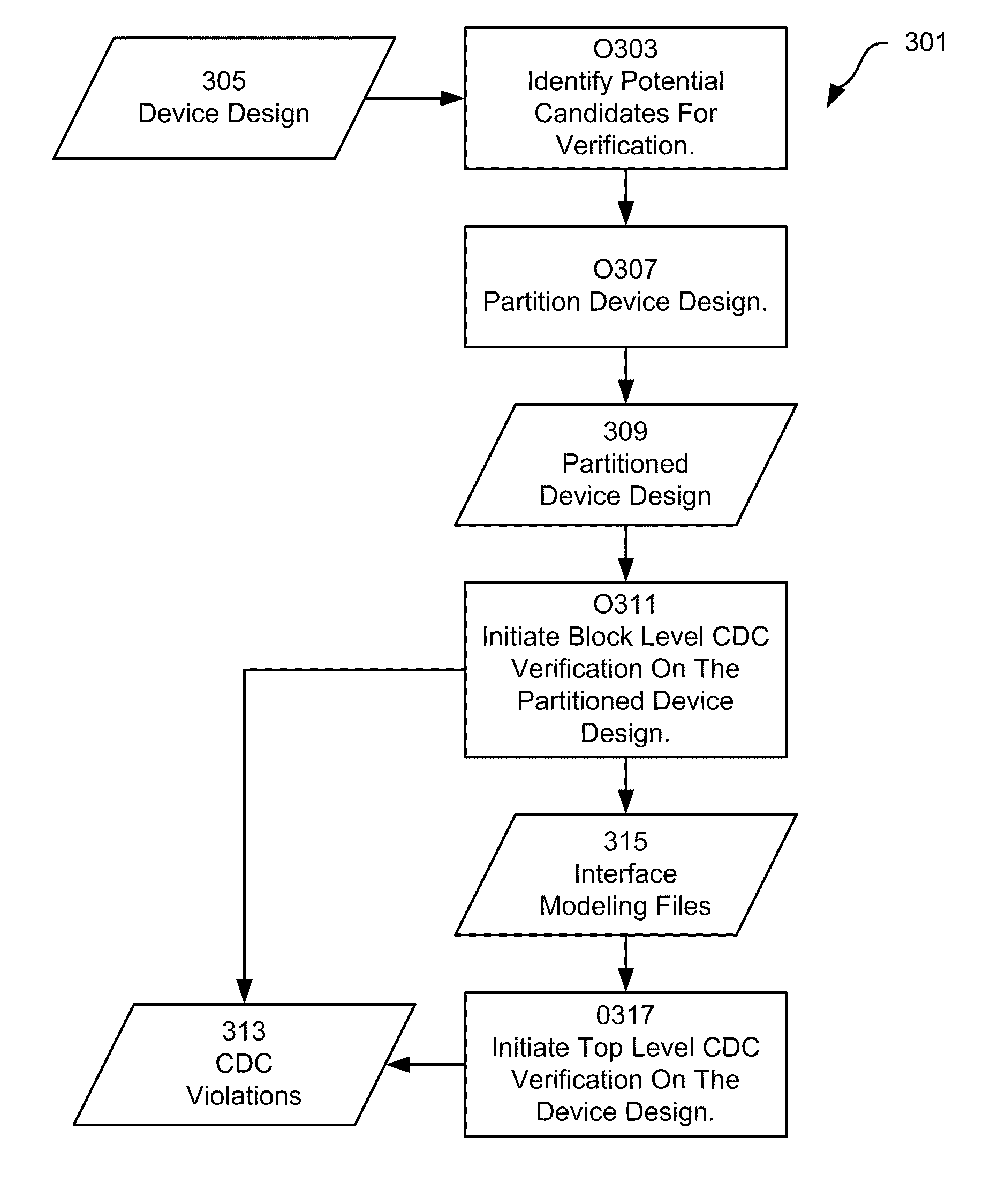
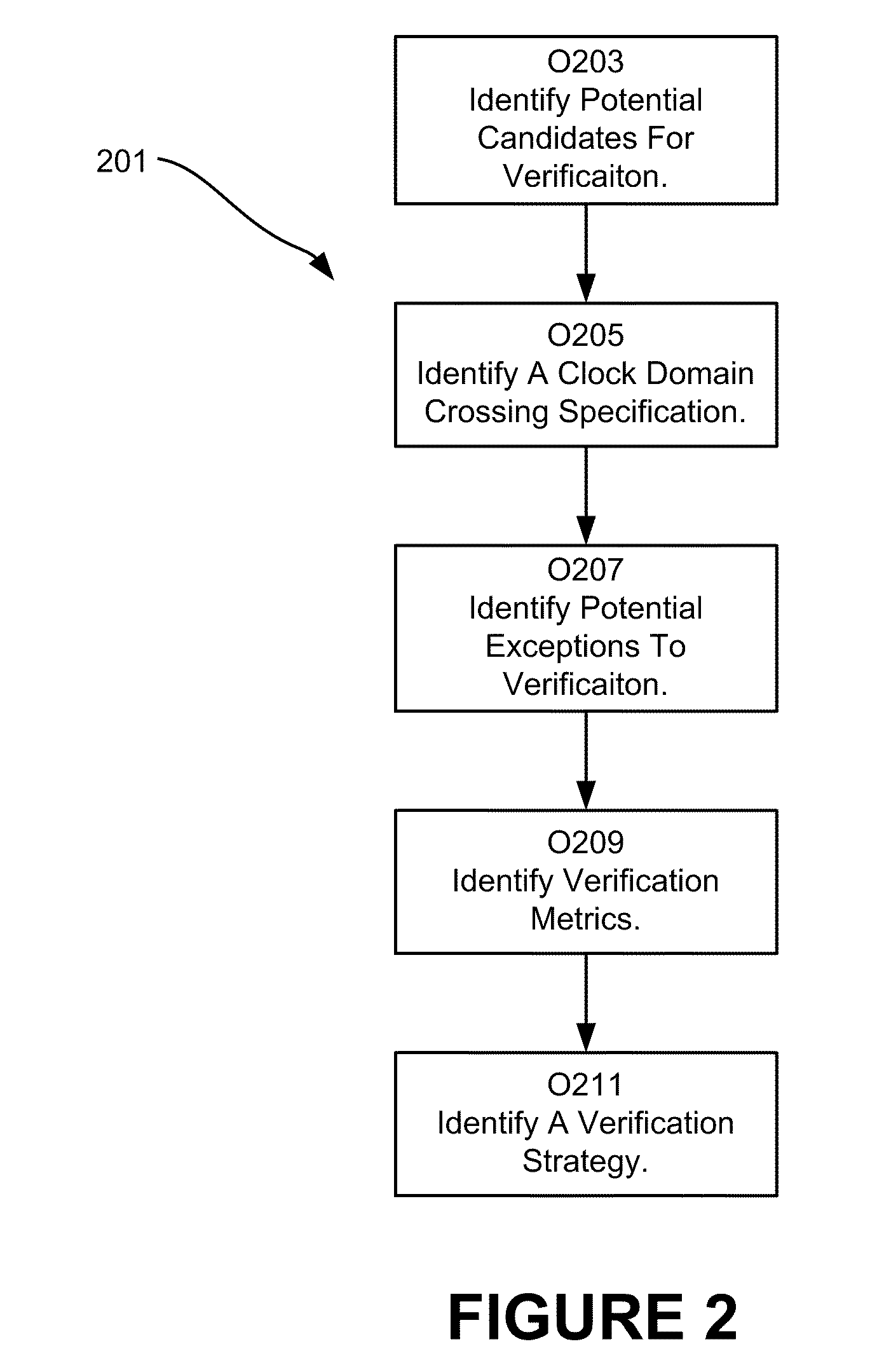
The invention provides for the hierarchical verification of clock domain crossings. In various implementations of the invention, a device design is partitioned into blocks. Subsequently, a block level clock domain crossing verification process is performed on selected ones of the blocks. Verification interface files are generated by the block level clock domain crossing process. After which, a top level clock domain crossing verification process is performed over the entire design. In various implementations, the top level clock domain crossing verification process utilizes the verification interface files to verify clock domain crossing signals between blocks. Additionally, in some implementations, blocks not verified during block level verification are verified during top level verification. With some implementations of the invention, the device design is partitioned based input from a user of the implementation. Furthermore, in various implementations, the specific clock domain crossing verification checks employed during block level verification and top level verification are specified by a user of the implementation.

Description

RELATED APPLICATIONS[0001]This applications claims priority under 35 U.S.C. §119 to U.S. Provisional Patent Application No. 61 / 112,396, entitled “Hierarchical Verification Of Clock Domain Crossings,” naming Ka-Kei Kwok et al. as inventors, and filed Nov. 7, 2009, which application is incorporated entirely herein by reference.FIELD OF THE INVENTION[0002]The invention relates to the field of electronic device design and verification. More specifically, various implementations of the invention relate to verification of clock domain crossings.BACKGROUND OF THE INVENTION[0003]Electronic circuits, such as integrated microcircuits, are used in a variety of products, from automobiles to microwaves to personal computers. Designing and fabricating microcircuit devices typically involves many steps, sometimes referred to as the “design flow.” The particular steps of a design flow often are dependent upon the type of microcircuit, its complexity, the design team, and the microcircuit fabricator...

Claims


Application Information

Patent Timeline
Patent Type & Authority Applications(United States)
IPC IPC(8): G06F17/50
CPCG06F17/504G06F17/5045G06F2217/62G06F30/3323G06F30/396G06F30/30
Inventor KWOK, KA-KEI
Owner SIEMENS PROD LIFECYCLE MANAGEMENT SOFTWARE INC
Why Eureka
Try Eureka