
Arrangement to Determine a Static Moment of a Blade

a technology of static moment and arrangement, which is applied in the direction of measurement devices, structural/machine measurement, instruments, etc., can solve the problems of inflexible weighing system, excessive wear of wind turbine components, and cracks on the rotor, so as to reduce the chain of tolerances, and reduce the weighing process. effect of tolerances

Inactive Publication Date: 2010-09-30
SIEMENS AG
View PDF4 Cites 14 Cited by
  • Summary
  • Abstract
  • Description
  • Claims
  • Application Information

AI Technical Summary

Benefits of technology

[0012]It is therefore the aim of the invention, to provide an improved arrangement to determine the static-moment of a blade of a wind-turbine, which allows to determine the static-moment with less expensive efforts.
[0025]The invention allows to determine the static-moment of a blade in an easy and cheap manner.
[0026]The invention allows to reuse the area, which is needed for the determination of the static-moment, for other purposes as its components can be removed easily when the measurement is done.
[0030]The invention allows to reduce tolerances in the weighing process as less components are needed compared with the state of the art. Therefore a resulting chain of tolerances are reduced.

Problems solved by technology

Instabilities result in extraordinary wear of wind-turbine-components.
Over time cracks may occur on the rotor, the nacelle, the tower, the bearing and also to other primary components of the wind turbine because of the unbalanced mass of the rotating blades.
The two scales have to perform the weight-measurement of the huge blade very accurately, so they are very expensive.
This leads to an inflexible weighing-system—so valuable production-area is allocated constantly, even if no blade-weighing needs to be performed.
Here the same problems as stated above will occur.
An exact placement of the blade is needed and this is difficulty to achieve.

Method used


Image

  • Arrangement to Determine a Static Moment of a Blade
  • Arrangement to Determine a Static Moment of a Blade

Examples


Embodiment Construction

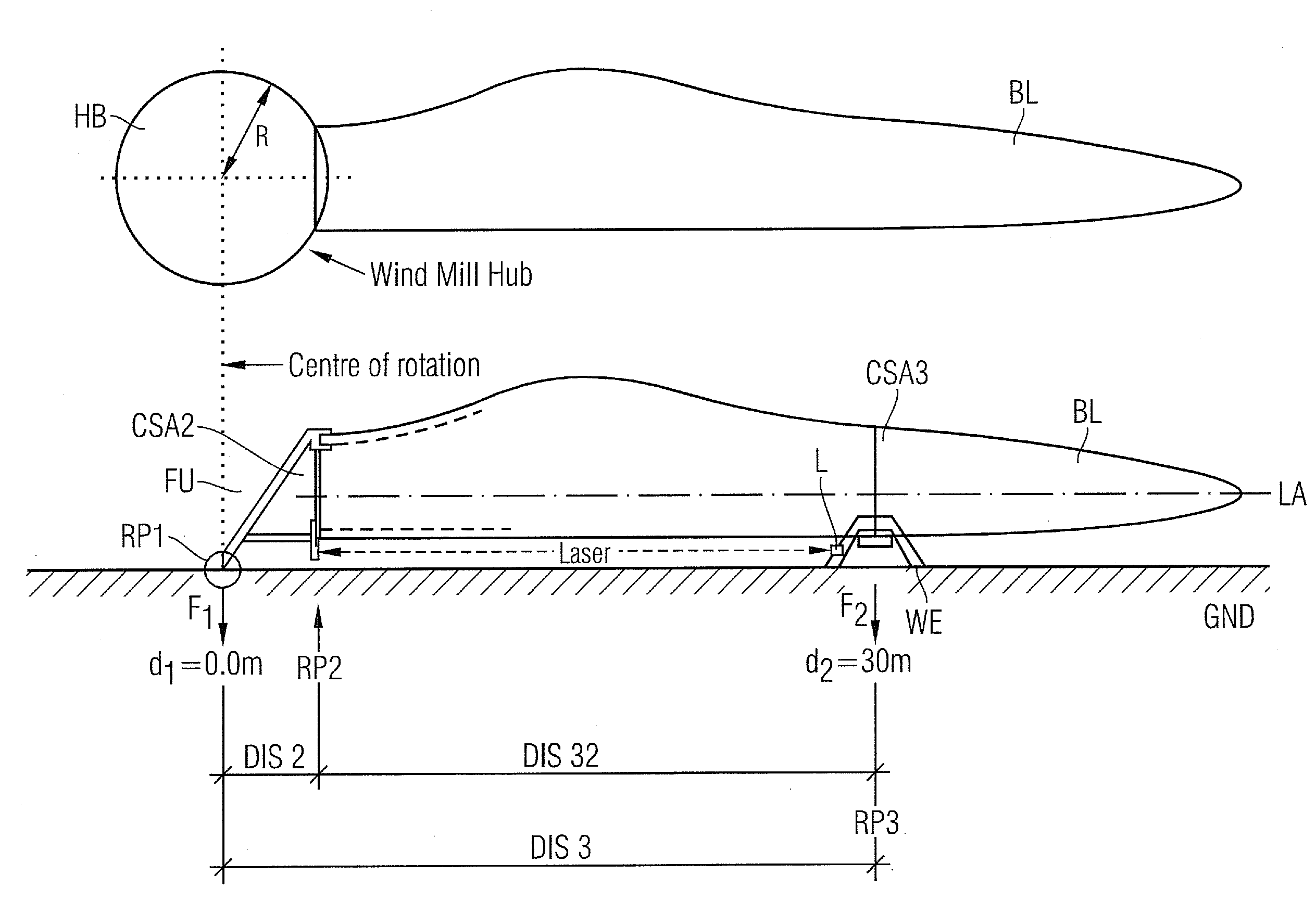
[0033]A fixation-unit FU is used to hold the blade BL in a mainly horizontal position. So the longitudinal-axis LA of the blade BL is mainly parallel to the ground GND.

[0034]The fixation-unit FU shows a first reference-point RP1, which is used as a center of rotation of the fixation-unit. So the fixation unit FU is mounted pivotable around the first reference-point RP1.

[0035]The fixation-unit FU shows a second reference-point RP2, which has a predetermined distance DIS2 to the first reference-point RP1. The distance DIS2 between the two reference-points is equal to a radius R of a hub HB, which is planned to carry the blade BL later at a wind-turbine-site (please refer to the sketch shown in top of FIG. 1).

[0036]The second reference-point RP2 is part of a cross-sectional-area CSA2 of the fixation-unit FU, while this area CSA2 is orthogonal to the longitudinal-axis LA and while this cross-sectional-area CSA2 is prepared and used to carry the root-end of the blade BL.

[0037]Because of ...


PUM


Abstract

A root-end of the blade is connectable to a fixation unit which is pivotably mounted around a first reference-point. A first static moment of the fixation unit without the blade connected is determined in reference to a first reference-point, while the first static-moment is acting on the fixation-unit at the first distance. A second static-moment of the fixation unit and the connected blade is determined at a second distance in reference to the first reference-point, while the second distance is allocated to a cross-section of the blade. The first and the second static-moment are used to calculate the static-moment of the blade.

Description

CROSS REFERENCE TO RELATED APPLICATIONS[0001]This application claims priority of European Patent Office application No. 09004278.9 EP filed Mar. 25, 2009, which is incorporated by reference herein in its entirety.FIELD OF INVENTION[0002]The invention relates to an arrangement to determine a static moment of a blade, especially of a wind-turbine-blade.BACKGROUND OF INVENTION[0003]A wind-turbine rotor has to be balanced to ensure the lifetime of the wind-turbine. For this each blade, which has to be mounted on a hub of the rotor, has to affect the hub with the same gravity-moment or static-moment.[0004]If the blades differ in their static-moments the wind turbine is affected by the rotating blades irregular. Instabilities result in extraordinary wear of wind-turbine-components. Over time cracks may occur on the rotor, the nacelle, the tower, the bearing and also to other primary components of the wind turbine because of the unbalanced mass of the rotating blades. In worst case the lif...

Claims


Application Information

Patent Timeline
Patent Type & Authority Applications(United States)
IPC IPC(8): G01M1/12
CPCG01M1/12
Inventor PEDERSEN, DAVID STIEN
Owner SIEMENS AG
Learn More