
Actuator apparatus

a technology of actuator and actuator, which is applied in the direction of piezoelectric/electrostriction/magnetostriction machines, magnetostrictive devices, and gearing. it can solve the problem of high structural outlay

Active Publication Date: 2010-09-30
ETO MAGNETIC GMBH
View PDF8 Cites 16 Cited by
  • Summary
  • Abstract
  • Description
  • Claims
  • Application Information

AI Technical Summary

Benefits of technology

The invention is a type of actuator that can tilt and / or pivot in response to electrical activation. It is made up of two expansion units, each containing magnetic shape-memory alloy material, which can expand or contract in response to the electrical activation and a magnetic field. The drive element, which can be tilted and / or pivoted in different directions, is connected to the expansion units. The actuator can achieve a large number of tilting and / or pivoting positions without power being supplied, and it can also have a bistable effect, meaning it can hold its position without power. The actuator can be used in various applications, such as in motor-vehicles or air-conditioning, where it can provide simple and reliable operation with short switching times and high tolerance to environmental conditions.

Problems solved by technology

The disadvantage of a known apparatus of this type is initially the high level of structural outlay; four coils have to be used in the abovementioned prior art in order to move a relatively large rotary armature as the drive element.

Method used


Image

  • Actuator apparatus
  • Actuator apparatus
  • Actuator apparatus

Examples


Embodiment Construction

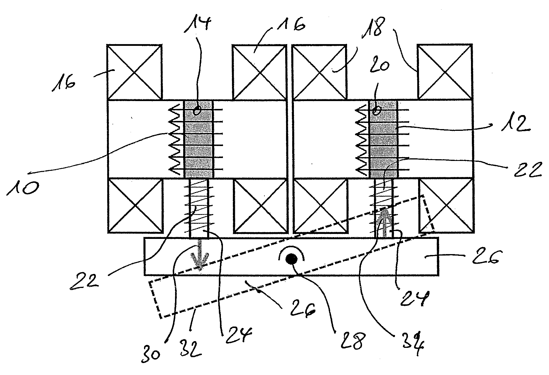
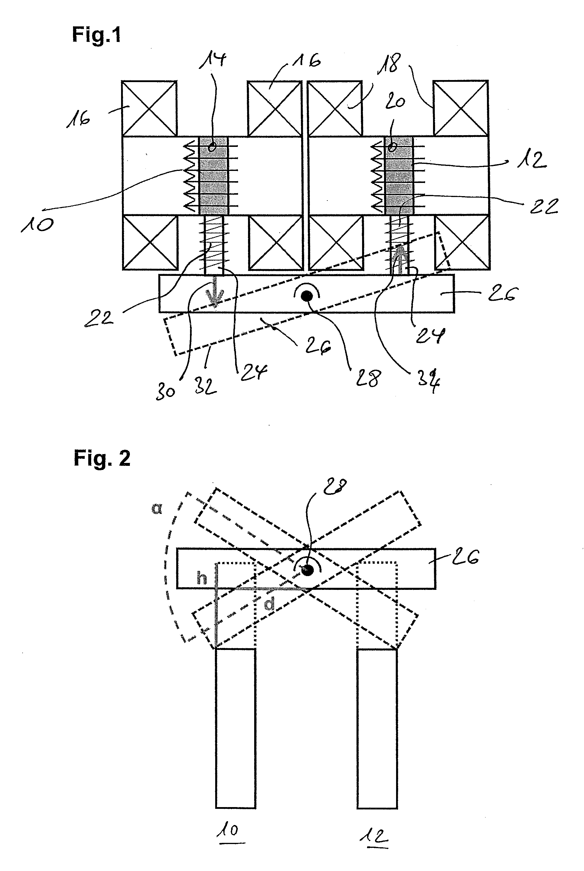
[0019]FIG. 1 illustrates, in the schematic illustration through a longitudinal section, the manner of operation of a first exemplary embodiment. A pair of expansion units 10, 12 is realized by means of a magnetic shape-memory alloy material (for example NiMnGa (as a mono-, multi- or polycrystal), magnetic field strength of approximately 11). Materials of this type are known from the prior art and are distinguished in that they experience a change in length in response to an applied magnetic field; in practice, this change in length is typically approximately 4% to 6%, up to approximately 10%, of the elongation of such a material in relation to the extension direction.

[0020]As shown in FIG. 1, the shape-memory alloy material 10 can be expanded by a magnetic field (group of arrows 14), this magnetic field being generated by a coil pair 16 in response to an electrical activation. Analogously, a second coil pair 18 generates a magnetic field (group of arrows 20) for the second expansion...


PUM


Abstract

Actuator apparatus having a drive element (26) which can tilt and / or pivot in a predetermined manner in response to electrical activation and which is formed such that it can be contacted by an output partner in order to transmit mechanical drive energy, wherein the drive element, as a connection element, is operatively connected to two expansion units (10, 12; 40, 42), which are formed by means of magnetic shape-memory alloy material, such that the connection element executes a tilting and / or pivoting movement in response to an expansion or contraction movement of one of the expansion units, expansion or contraction movement being produced by the electrical activation and also a magnetic field which is generated by said electrical activation.

Description

BACKGROUND OF THE INVENTION[0001]The present invention relates to an actuator apparatus having a drive element which can tilt and / or pivot in a predetermined manner in response to electrical activation and which is formed such that it can be contacted by an output partner in order to transmit mechanical drive energy.[0002]An apparatus of this type is generally known from the prior art and is used, for example, in connection with rotary actuation tasks.[0003]Reference is made, by way of example, to WO 03 / 019582 A1 as the prior art which forms this generic type. Said document describes an electromagnetic rotary actuator which is used, in particular, in the automotive industry for moving a throttle valve for internal combustion engines. In this known prior art, a drive element in the form of a tilting or pivoting lever is held such that it can rotate about a bearing shaft, and, in response to a suitable supply of power to the coil system, the pivotable drive element is moved to a desir...

Claims


Application Information

Patent Timeline
Patent Type & Authority Applications(United States)
IPC IPC(8): F16H21/44
CPCF02D9/1065Y10T74/18888H02N2/10H01L41/12H10N35/00
Inventor LAUFENBERG, MARKUS
Owner ETO MAGNETIC GMBH
Learn More