Screen printing apparatus

a technology of screen printing and screen, which is applied in the direction of printing, coatings, printed circuit manufacture, etc., can solve the problems of difficulty in parallel providing two screen printing apparatuses, and achieve the effect of not affecting and being easy to arrang

Active Publication Date: 2010-09-30
PANASONIC CORP
View PDF15 Cites 26 Cited by
  • Summary
  • Abstract
  • Description
  • Claims
  • Application Information

AI Technical Summary

Benefits of technology

[0016]Since the two substrate introduction portions, the two printing portions, and the two substrate discharge portions constituting the two screen printers are respectively formed at a position symmetrical to each other with respect to the perpendicular symmetrical plane extending in the substrate transportation direction in the component mounting line, it is easy to arrange the respective portions of the screen printers. Additionally, since each printing portion of the screen printers is provided at a position further from the perpendicular symmetrical plane than the substrate discharge portion, even when the interval between the two substrate discharge portions cannot be set to be narrow so as to correspond to the interval between the two substrate transportation paths constituting the component mounting apparatus as the apparatus provided on the downstream side, it is possible to arrange the two printing portions at a position symmetrical to each other so as not to interfere with each other.

Problems solved by technology

In this case, since the screen printing apparatus cannot continuously perform the screen printing to the different types of substrates, it is necessary to provide two screen printing apparatuses in parallel to each other at a position on the upstream side of the component mounting apparatus.
However, since the interval between the two substrate transportation paths constituting the component mounting apparatus is very narrow, it is very difficult to provide two screen printing apparatuses in parallel so that the substrate discharge portions of the screen printing apparatuses are opposed to the two substrate transportation paths of the component mounting apparatus.
However, since the different types of masks are provided in serial to the one substrate transportation path of the screen printing apparatus, it is necessary to provide a complex substrate supply system to the substrate transportation path so as to supply the different substrates alternatively or once in several substrates.

Method used


Image

  • Screen printing apparatus
  • Screen printing apparatus
  • Screen printing apparatus

Examples


Embodiment Construction

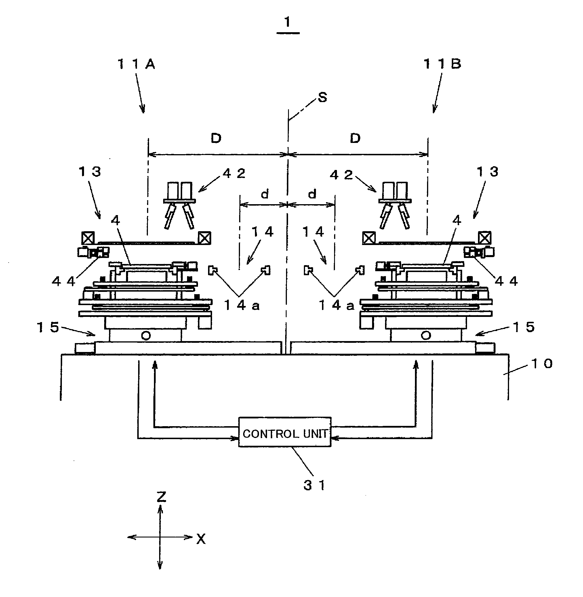
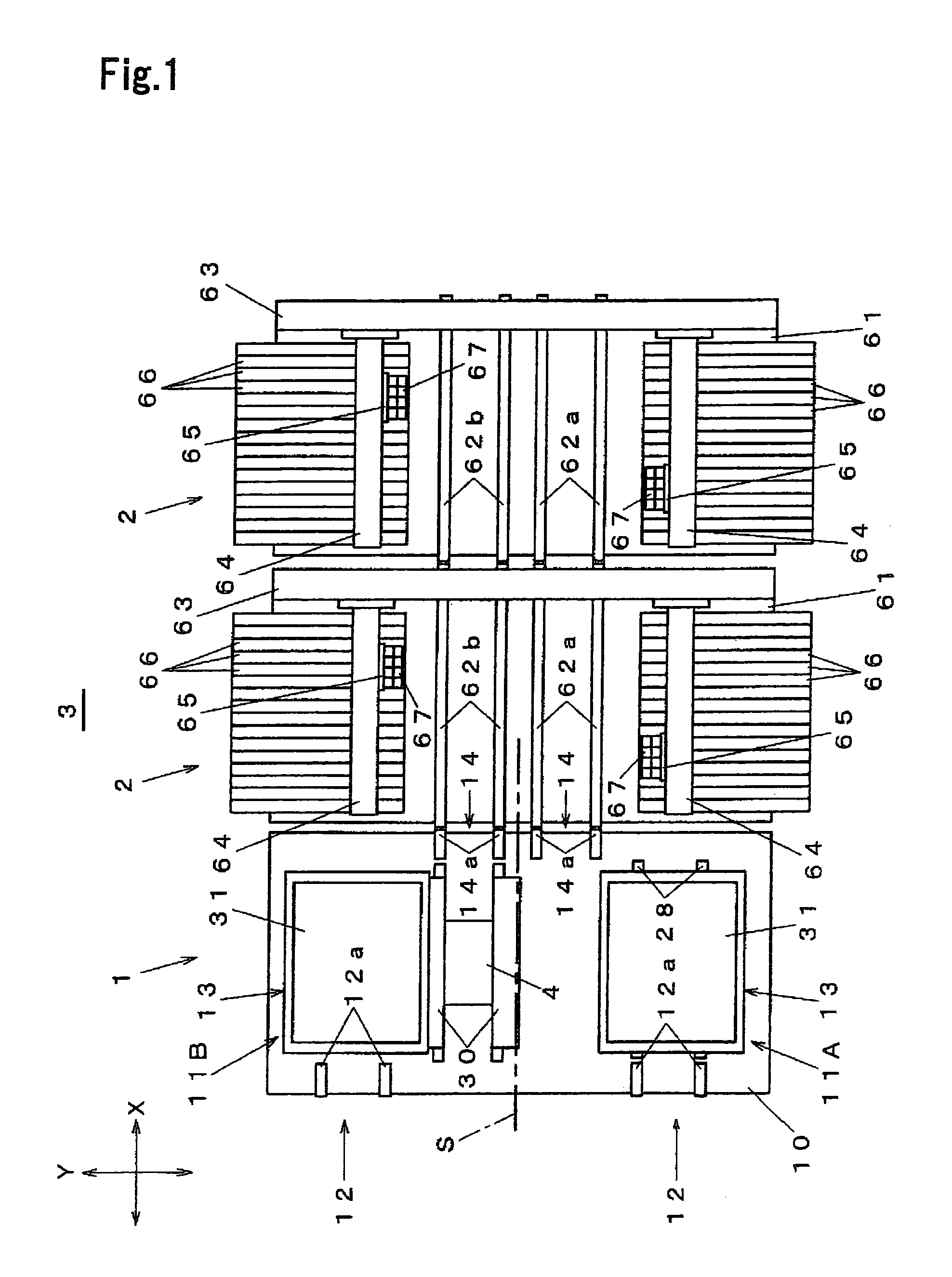
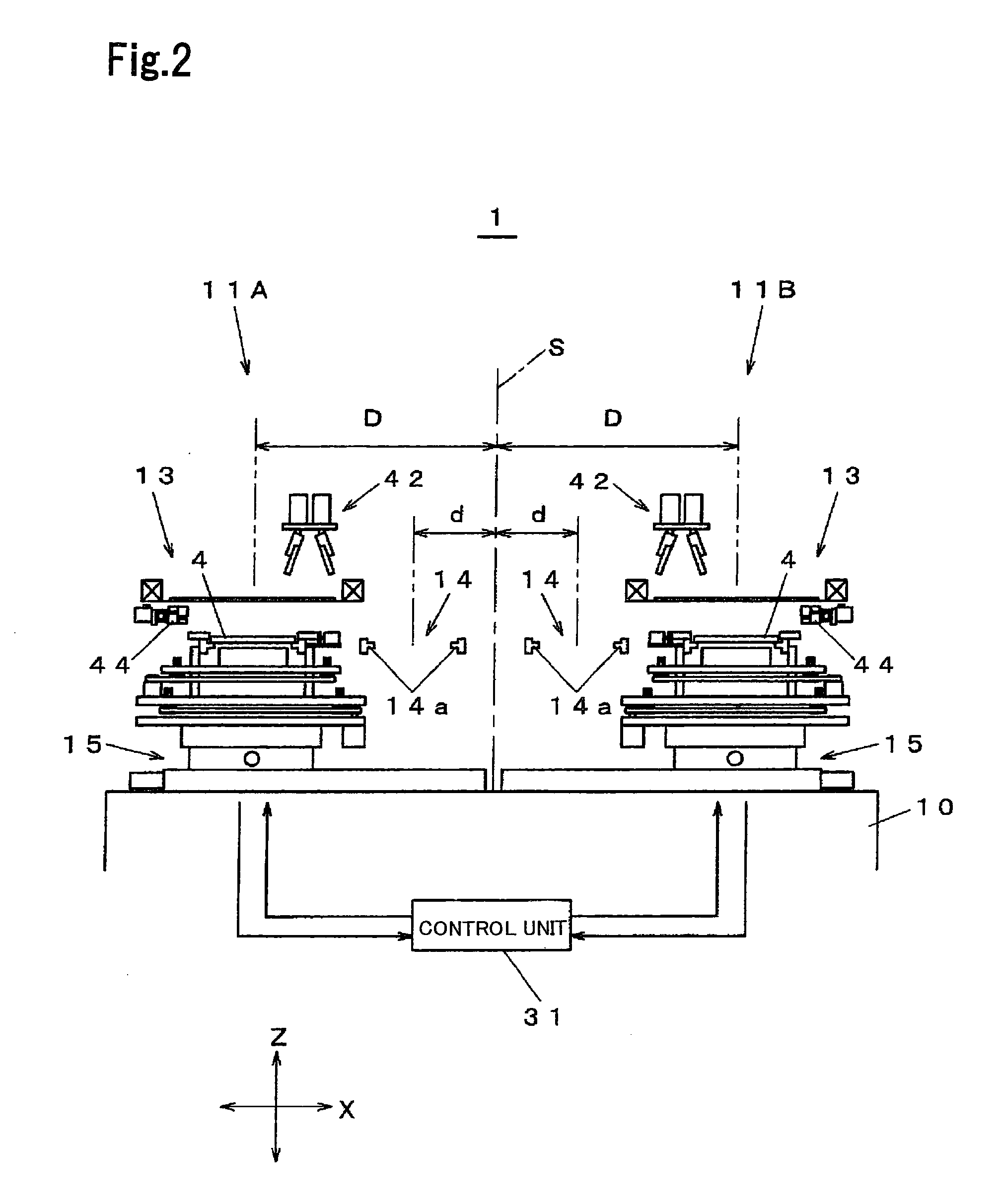
[0024]Hereinafter, an embodiment of the invention will be described with reference to the accompanying drawings. FIG. 1 is a top view showing a component mounting line according to an embodiment of the invention. FIG. 2 is a front view showing a screen printing apparatus according to the embodiment of the invention. FIG. 3 is a front view showing a screen printer of the screen printing apparatus according to the embodiment of the invention. FIG. 4 is a side view showing the screen printer of the screen printing apparatus according to the embodiment of the invention. FIGS. 5A and 5B are explanatory views showing an operation of the screen printer of the screen printing apparatus according to the embodiment of the invention. FIGS. 6A to 6F are explanatory views showing the operation of the screen printer of the screen printing apparatus according to the embodiment of the invention.

[0025]In FIG. 1, a screen printing apparatus 1 is mounted to a component mounting line 3 together with a ...


PUM


Abstract

The screen printing apparatus includes two screen printers 11A and 11B each including a substrate introduction portion 12 by which a substrate 4 is introduced from the upstream side of the component mounting line 3, a printing portion 13 which performs a screen printing to the introduced substrate 4, a substrate discharge portion 14 by which the substrate 4 subjected to the screen printing is discharged to the downstream side, and a substrate moving stage 15 which receives the introduced substrate 4 so as to position the substrate 4 with respect to the printing portion 13 and to move the substrate 4 subjected to the screen printing to the substrate discharge portion 14. The two substrate introduction portions 12, the two printing portions 13, and the two substrate discharge portions 14 are arranged symmetrically to each other with respect to a perpendicular symmetrical plane S extending in a transportation direction of the substrate 4 in the component mounting line 3, respectively. Each printing portion 13 is provided at a position further from the perpendicular symmetrical plane S than the substrate discharge portion 14.

Description

TECHNICAL FIELD[0001]The present invention relates to a screen printing apparatus which is mounted to a component mounting line to perform a screen printing to a substrate introduced from the upstream side and to discharge the substrate to the downstream side of the component mounting line.BACKGROUND ART[0002]A screen printing apparatus is mounted to a component mounting line together with a component mounting apparatus or an attachment apparatus to perform a screen printing using cream solder or conductive paste to a substrate introduced from the upstream side and to discharge the substrate to an apparatus provided on the downstream side of the component mounting line. In general, the screen printing apparatus is disposed on the upstream side of the component mounting apparatus and the substrate subjected to the screen printing is directly or indirectly transferred from a substrate discharge portion of the screen printing apparatus to a substrate transportation path of the componen...

Claims


Application Information

Patent Timeline
Patent Type & Authority Applications(United States)
IPC IPC(8): B05C17/08
CPCB41F15/08B41F15/0818H05K13/0465H05K3/1216H05K3/0097
Inventor NAGAO, KAZUHIDE
Owner PANASONIC CORP
Why Eureka
Try Eureka