Anesthetic vaporizer

a technology of anesthetic vaporizer and vaporizer body, which is applied in the direction of combustion types, lighting and heating apparatus, instruments, etc., can solve the problems of reducing the evaporation speed of the anesthetic agent, reducing the evaporation speed of the liquid, and gradually lowering the temperature of the vaporizer

Active Publication Date: 2010-09-30
SHENZHEN MINDRAY BIO MEDICAL ELECTRONICS CO LTD
View PDF10 Cites 3 Cited by
  • Summary
  • Abstract
  • Description
  • Claims
  • Application Information

AI Technical Summary

Benefits of technology

[0009]The technical problem to be solved by the present invention is to overcome the disadvantages in the prior art and to provide an anesthetic vaporizer that can provide a steady output of concentration of the anesthetic vapor in the mixed gas.

Problems solved by technology

When the vaporizer is used continuously, the temperature of the vaporizer drops since the anesthetic agent has to absorb heat to vaporize, which in turn reduces the evaporation speed of the anesthetic agent since the evaporation speed of the liquid decreases as the temperature drops.
However, this kind of anesthetic vaporizer typically has the following disadvantages: (1) Although there is a temperature compensation unit, since the temperature compensation unit and the pressure compensation unit are independent to each other, then when in use, the temperature compensation unit is unable to change the temperature of the vaporizer and the pressure compensation unit is unable to serve the function of adjusting temperature, the two units cannot be combined together, resulting in that when in use, the temperature of the vaporizer will gradually drops and accordingly the vaporization speed of the anesthetic agent will slow down and the deviation of the concentration of the anesthetic vapor in the outputted mixed gas from the set concentration will be increased, over time; (2) When being placed outside the vaporizer, the pressure compensation unit occupies the space outside the vaporizer so that the structure of the vaporizer is not compact, and when being placed inside the vaporizer, the pressure compensation unit is required to be assembled together with other units so that the structure and assembly are complicated.

Method used


Image

  • Anesthetic vaporizer
  • Anesthetic vaporizer
  • Anesthetic vaporizer

Examples


Embodiment Construction

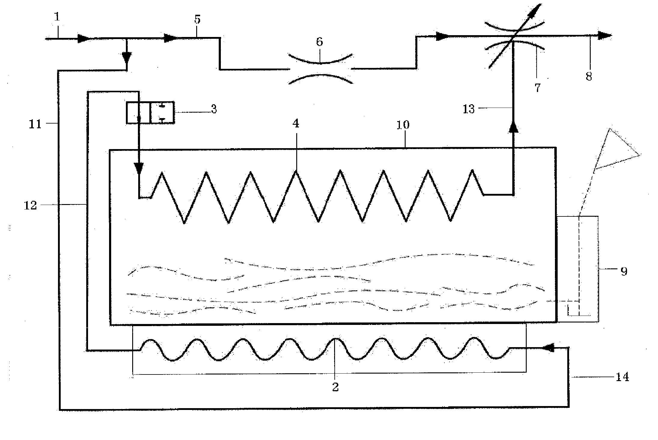
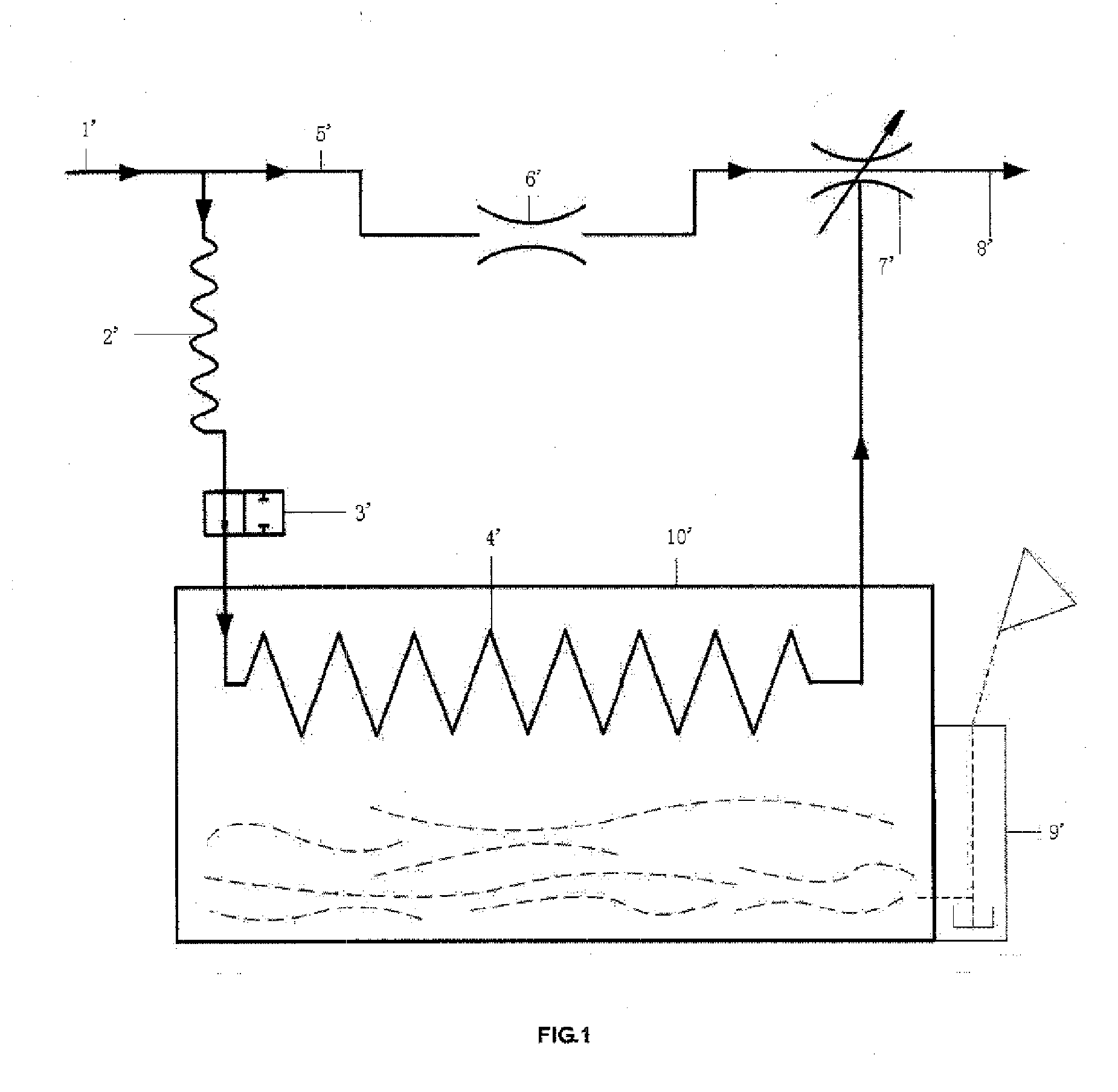
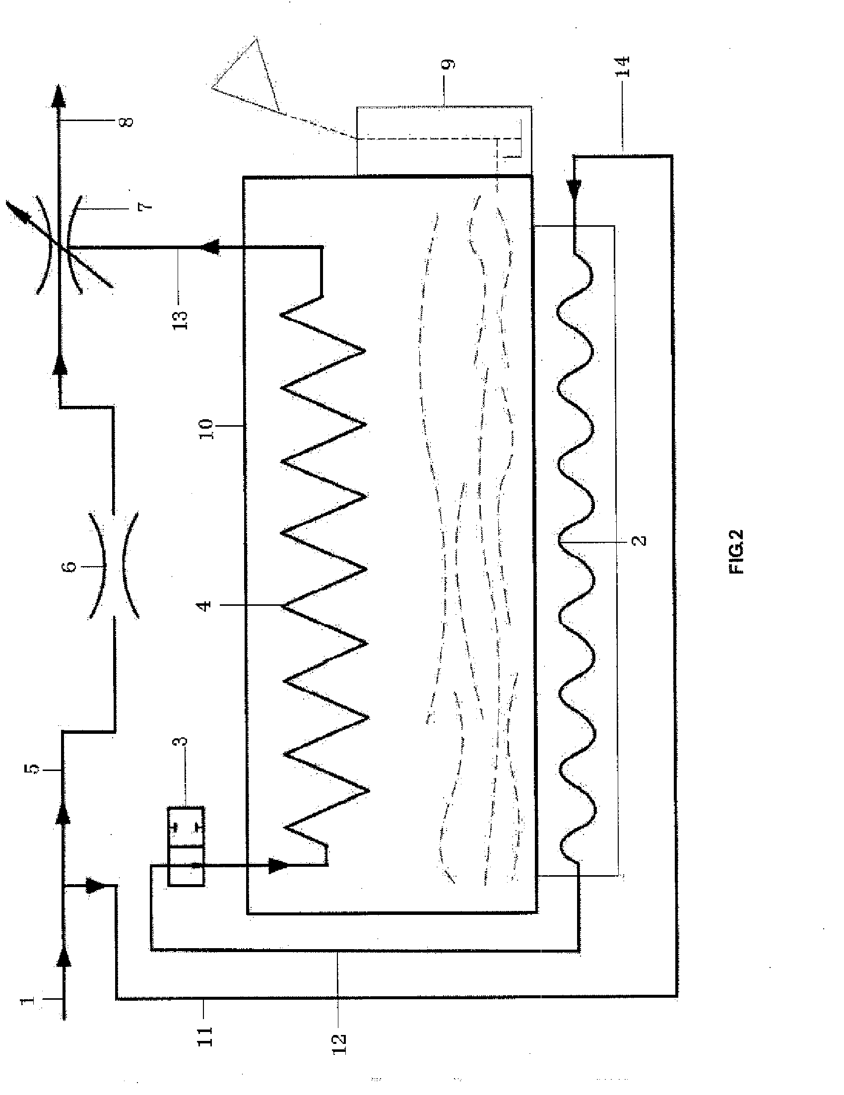
[0022]As illustrated in FIGS. 2-5, an anesthetic vaporizer according to an embodiment of the present invention comprises a fresh gas inlet 1, a mixed gas outlet 8, a vaporizing chamber 10, a filling unit 9, a first gas branch circuit 5 and a second gas branch circuit 14. The fresh gas inlet 1 is used to receive fresh gas. The mixed gas outlet 8 is used to output the mixed gases of fresh gas and anesthetic vapor. The vaporizing chamber 10 may be made of metal having good heat conductance and has a reservoir for storing anesthetic agent. The filling unit 9 is used to injecting anesthetic agent into the reservoir of the vaporizing chamber and communicated with the reservoir through a passage.

[0023]The first gas branch circuit 5 is provided with a temperature compensation unit 6 and a concentration control unit 7. The temperature compensation unit 6, which may be implemented as a valve body that can change the vent aperture of the first gas branch circuit 5, adjusts the vent aperture of...


PUM


Abstract

An anesthetic vaporizer is disclosed herein which comprises a fresh gas inlet, a mixed gas outlet, a first gas branch circuit, a second gas branch circuit and a vaporizing chamber. The vaporizing chamber has a reservoir for containing an anesthetic agent. The first gas branch circuit connects the fresh gas inlet and the mixed gas outlet. The second gas branch circuit comprises a first pneumatic circuit, a pressure compensation unit, a second pneumatic circuit, a wick unit and a third pneumatic circuit. The pressure compensation unit has a curved, continuous and sealed vent slot. The wick unit has an immersion portion which is directly contacted with the anesthetic agent in the reservoir. The fresh gas inlet, the first pneumatic circuit, the vent slot, the second pneumatic circuit, the wick unit, the third pneumatic circuit and the mixed gas outlet are sequentially connected with one another. The pressure compensation unit is provided in the reservoir and has a heat conductor which is directly contacted with the anesthetic agent to transfer heat. The vent slot is formed in the heat conductor. The anesthetic vaporizer according to the invention can stabilize the concentration of the anesthetic vapor in the outputted mixed gas.

Description

CROSS-REFERENCE TO RELATED APPLICATIONS[0001]The present application claims priority to Chinese Patent Application No. 200810216455.1, filed on Sep. 28, 2008, which is hereby incorporated by reference in its entirety.FIELD OF THE INVENTION[0002]The present invention relates to an anesthetic vaporizer.BACKGROUND OF THE INVENTION[0003]An anesthetic vaporizer is an apparatus that can be used to effectively vaporize a liquid anesthetic agent, and can precisely input the liquid anesthetic agent at a certain concentration into an anesthesia breathing circuit, which is able to eliminate the influences of changes in temperature and pressure and the like on the concentration output thereof.[0004]As illustrated in FIG. 1, the anesthetic vaporizer typically comprises a fresh gas inlet 1′, a pressure compensation unit 2′, a fresh gas control valve 3′, a wick unit 4′, a bypass circuit 5′, a temperature compensation unit 6′, a concentration control unit 7′, a mixed gas outlet 8′, a filling unit 9...

Claims


Application Information

Patent Timeline
IPC IPC(8): A61M16/01
CPCA61M16/18A61M2205/3372A61M16/183
Inventor CHEN, DONGHUAGONG, DAOMINGWANG, WEI
Owner SHENZHEN MINDRAY BIO MEDICAL ELECTRONICS CO LTD
Why Eureka
Try Eureka