Thermal interface material and method for manufacturing same

a technology of thermal interface materials and materials, applied in the field of thermal interface materials, can solve problems such as still being unsatisfactory for some applications

Active Publication Date: 2010-09-30
TSINGHUA UNIV +1
View PDF7 Cites 26 Cited by
  • Summary
  • Abstract
  • Description
  • Claims
  • Application Information

AI Technical Summary

Problems solved by technology

However, even though the thermal interface structure's thermal conductivit

Method used


Image

  • Thermal interface material and method for manufacturing same
  • Thermal interface material and method for manufacturing same
  • Thermal interface material and method for manufacturing same

Examples


Embodiment Construction

[0022]Embodiments of the present invention will now be described in detail below and with reference to the drawings. The exemplifications set out herein illustrate various preferred embodiments of the invention, in various forms, and such exemplifications are not to be construed as limiting the scope of the invention in any manner.

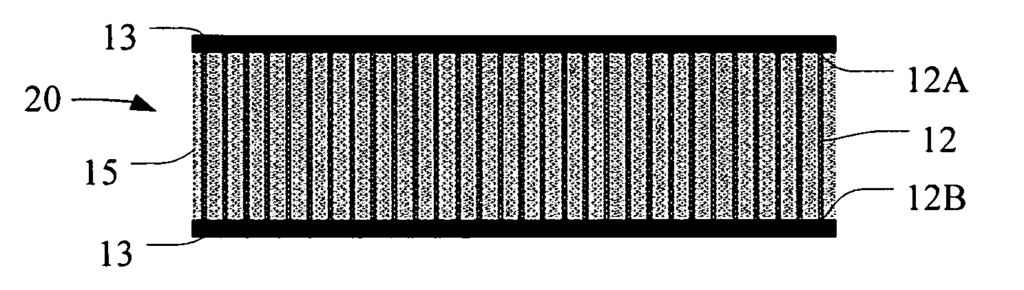
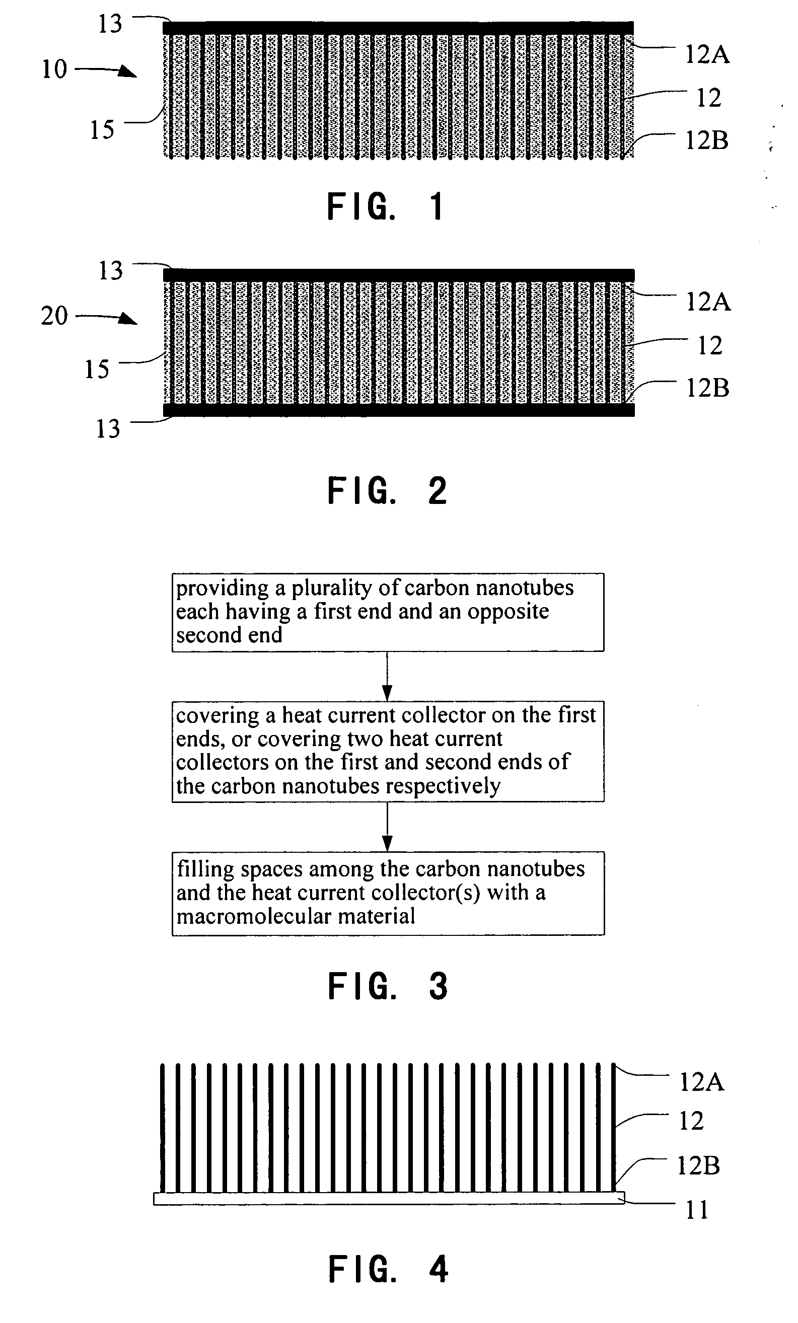
[0023]Referring to FIG. 1, a thermal interface material 10 according to a first preferred embodiment is shown. The thermal interface material 10 includes a plurality of carbon nanotubes 12 each having a first end 12A and an opposite second end 12B, a heat collector or a heat current collector 13 covering the first ends 12A of the carbon nanotubes 12, and a macromolecular material 15 filled in spaces among the carbon nanotubes 12 and heat current collector 13. The heat current collector 13 extends along a predetermined plane in which the second end 12B of each carbon nanotubes 12 reaches to commonly define.

[0024]The plurality of carbon nanotubes 12 can be i...


PUM


Abstract

One embodiment of a thermal interface material includes a plurality of carbon nanotubes each having a first end and an opposite second end, a heat current collector covering one of the first ends and the second ends of the carbon nanotubes, and a macromolecular material filled in spaces between the carbon nanotubes and heat current collector. A method for manufacturing a thermal interface material is also provided.

Description

CROSS-REFERENCE TO RELATED APPLICATIONS[0001]This application is related to six corresponding U.S. patent applications having the following titles, serial numbers and filing dates: “THERMAL INTERFACE MATERIAL AND METHOD FOR MANUFACTURING SAME” with application Ser. No. 11 / 024,513, filed on Dec. 28, 2004; “METHOD FOR MANUFACTURING CARBON NANOTUBES WITH UNIFORM LENGTH” with application Ser. No. 11 / 025,160, filed on Dec. 28, 2004; “THERMAL INTERFACE MATERIAL AND METHOD FOR MANUFACTURING SAME” with application Ser. No. 11 / 089,864, filed on Mar. 25, 2005; “THERMAL INTERFACE MATERIAL AND METHOD FOR MAKING SAME” with application Ser. No. 11 / 321,315, filed on Dec. 29, 2005; “THERMAL INTERFACE MATERIAL AND METHOD FOR MANUFACTURING SAME” with application Ser. No. 11 / 321,278, filed on Dec. 29, 2005; and “METHOD FOR MANUFACTURING A THERMAL INTERFACE MATERIAL” with application Ser. No. 11 / 321,316, filed on Dec. 29, 2005. Each of the six corresponding U.S. patent applications has the same assigne...

Claims


Application Information

Patent Timeline
IPC IPC(8): F28F7/00
CPCC09K5/14Y10S977/742Y10T428/30H01L2924/0002H01L2924/00
Inventor WU, YANGHUANG, HUALIU, CHANG-HONGFAN, SHOU-SHAN
Owner TSINGHUA UNIV
Why Eureka
Try Eureka