Heat exchanger using microporous hydrophobic membrane for strengthening heat exchange

A technology to strengthen heat exchange and heat exchangers, applied in the direction of heat exchanger types, indirect heat exchangers, lighting and heating equipment, etc.

Inactive Publication Date: 2009-11-11
INST OF ENGINEERING THERMOPHYSICS - CHINESE ACAD OF SCI
View PDF0 Cites 11 Cited by
  • Summary
  • Abstract
  • Description
  • Claims
  • Application Information

AI Technical Summary

Problems solved by technology

Membrane distillation technology has been used as a separation method since its inception, and no one has used it as a means to enhance heat transfer.

Method used


Image

  • Heat exchanger using microporous hydrophobic membrane for strengthening heat exchange
  • Heat exchanger using microporous hydrophobic membrane for strengthening heat exchange
  • Heat exchanger using microporous hydrophobic membrane for strengthening heat exchange

Examples


Embodiment 1

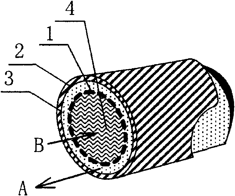
[0034] see figure 1 , the present invention utilizes microporous hydrophobic film to strengthen the heat exchanger of heat exchange, and the overall shape is a circular tube, and is mainly used for the object that needs to be cooled to be smaller particle or liquid material. The outer shell (metal tube 2 ) of the heat exchanger is the heat exchange surface, and the material of the metal tube 2 can be made of a heat conductor, such as but not limited to copper, iron, aluminum, stainless steel and the like. The inside of the metal tube 2 is divided into two parts by a hydrophobic microporous membrane 1 , a main flow channel 3 (ie, an annular channel outside the membrane) and an auxiliary flow channel 4 (ie, an annular channel inside the membrane). The microporous hydrophobic membrane of the present invention is a polytetrafluoroethylene (PTFE) membrane, the average diameter of membrane holes is 0.1mm, the porosity is 70%, and the membrane thickness is 0.2mm. The fluids of the m...

Embodiment 2

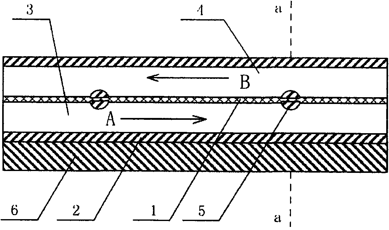
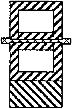
[0037] Taking the cooling of a high-power laser palladium strip as an example, the overall shape of the heat exchanger of the present invention is a rectangle, and its structure is shown in Figure 2. The shell 2 of the heat exchanger is made of brass. The interior of the heat exchanger is divided into two parts by a hydrophobic microporous membrane 1, the main flow channel 3 (that is, the lower pipe in Figure 2) and the auxiliary flow channel 4 (that is, the upper pipe in Figure 2), and the shell of the heat exchanger The wall thickness of 2 is 1 mm, the heights of the main flow channel and the auxiliary flow channel are respectively 2.5 mm, and the length and width are the same as those of the laser palladium bar 6 . The microporous hydrophobic membrane is a PTFE membrane, the average diameter of membrane pores is 0.1mm, the porosity is 70%, and the membrane thickness is 0.2mm. The main flow channel 3 of the heat exchanger is in contact with the palladium strip 6 of the laser...


PUM


Abstract

The invention discloses a heat exchanger using a microporous hydrophobic membrane for strengthening heat exchange. The shell of the heat exchanger is made of metal and fluid in the internal pipeline in the heat exchanger is divided by the microporous hydrophobic membrane into two parts flowing in opposite directions; fluid on a hot side of the heat exchanger contacts a heat exchange surface; the fluid on the hot side is heated by an external heat current, the temperature of the fluid on the hot side rises to generate a vapor pressure difference between two sides of the membrane, a working medium on high vapor pressure side evaporates and penetrates the membrane to flow to a low pressure side to achieve an effect of phase change heat transfer.

Description

technical field [0001] The invention relates to a phase change cooling device based on the principle of membrane distillation, in particular to a heat exchanger which utilizes a microporous hydrophobic membrane to enhance heat exchange. Background technique [0002] Since the latent heat is much larger than the sensible heat, the phase-change heat transfer of the same working fluid is more efficient than the single-phase heat transfer. For the cooling process, the gasification of the cooling working fluid during the heat exchange process will help improve total heat transfer coefficient. However, the condition for a liquid to vaporize is that its saturated vapor pressure is higher than its partial pressure in the gas phase, and this condition can usually only be achieved by raising the temperature or lowering the pressure. The most commonly used heat transfer medium in engineering is water. Under the conditions of normal pressure and slightly higher than room temperature, i...

Claims


Application Information

Patent Timeline
Patent Type & Authority Applications(China)
IPC IPC(8): F28D7/10F28D15/02B01D61/36
Inventor 梁世强陈亮淮秀兰
Owner INST OF ENGINEERING THERMOPHYSICS - CHINESE ACAD OF SCI
Why Eureka
Try Eureka