
Protective cover for a hand-held electronic device

Inactive Publication Date: 2015-01-15
SUNON ELECTRONICS FOSHAN
View PDF7 Cites 41 Cited by
  • Summary
  • Abstract
  • Description
  • Claims
  • Application Information

AI Technical Summary

Benefits of technology

The present invention provides a protective cover for a hand-held electronic device that includes a cooling module to increase cooling efficiency during operation. The cover has a flow guiding portion to direct air currents from a cooling fan towards the device, ensuring ideal cooling. Additionally, the cover includes a controller and cell to drive the cooling fan, which can discharge heat energy generated by the controller and cell, reducing the device's operating temperature. Overall, the protective cover with cooling fan improves cooling efficiency and helps to keep the device cool during use.

Problems solved by technology

Furthermore, the need of miniaturization of products compresses the cooling space of the electronic elements, resulting in overheating of the hand-held electronic devices during operation.
The cooling efficiency of a hand-held electronic device is reduced if the hand-held electronic device is covered by a protective cover, resulting in unstable operation and adversely affecting the reliability of the hand-held electronic device.
The performances of the hand-held electronic device degrade such that the desired performances can not be provided and even causes malfunction.
Use of any of the above conventional protective covers will adversely affect the cooling efficiency of the hand-held electronic device in operation.
However, the protective covers are necessary for protecting the hand-held electronic devices to reduce damage, causing a dilemma to the user.
Thus, the heat energy generated during operation of the hand-held electronic device still accumulate in the specific area and continuously damage the reliability, performances, and service life of the hand-held electronic device.

Method used


Image

  • Protective cover for a hand-held electronic device
  • Protective cover for a hand-held electronic device
  • Protective cover for a hand-held electronic device

Examples


first embodiment

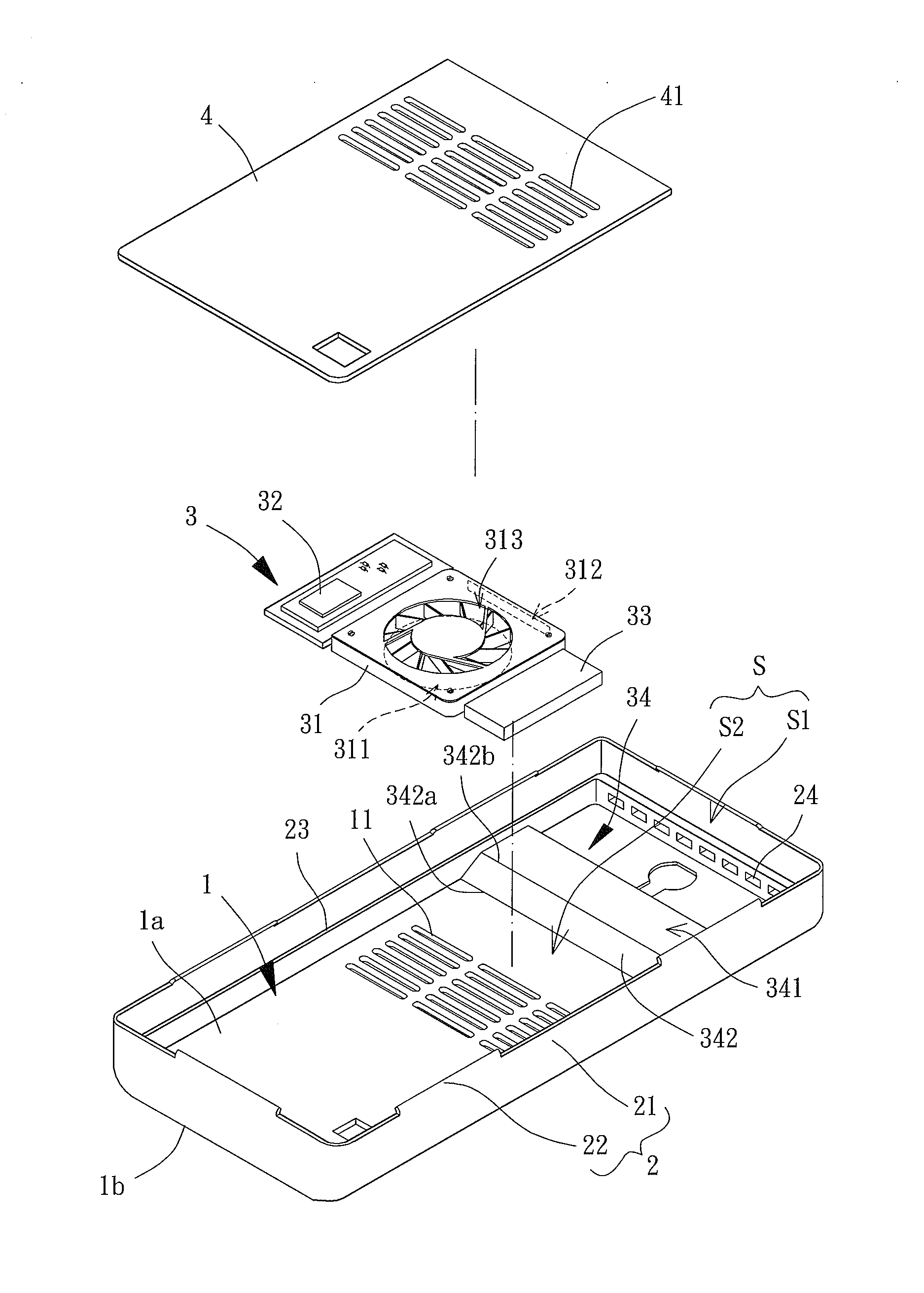
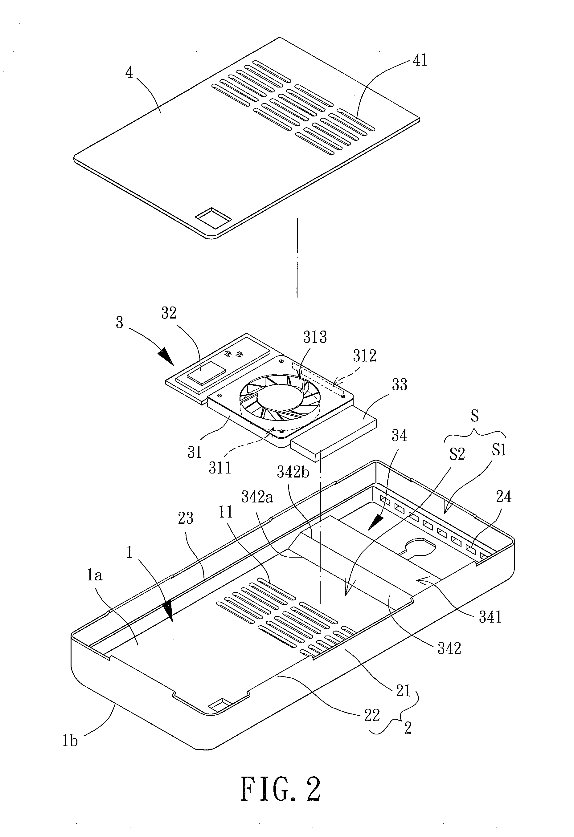
[0040]FIGS. 2 and 3 show a protective cover for a hand-held electronic device of a first embodiment according to the present invention. The protective cover includes a base 1, a positioning member 2, and a cooling module 3. The positioning member 2 is provided along a periphery of the base 1 such that the protective cover can be coupled to a hand-held electronic device E. The cooling module 3 is mounted to an inner side of the base 1. When the cooling module 3 operates, air currents are drawn to flow into and out of the base 1 to assist in cooling of the hand-held electronic device E. The base 1 and the positioning member 2 can be made of materials with excellent elasticity, such as rubber, silicon rubber, or resins. Alternatively, the base 1 and the positioning member 2 can be made of rigid materials, such as metal or plastics.

[0041]The base 1 includes an inner face 1a and an outer face 1b opposite to the inner face 1a. The base 1 is associated with a back board of the hand-held el...

second embodiment

[0052]FIG. 7 illustrates use of the protective cover of the second embodiment according to the present invention. The area E1 is aligned with the flow guiding portion 54 of the cooling fan 51 in the axial direction of the cooling fan 51. Preferably, the area E1 is aligned with the at least one spoiler 543 on the flow guiding face 541. By such an arrangement, the air currents blown out of the air outlet 512 are guided by the flow guiding face 541 to flow from a first edge 542a to a second edge 542b of at least one non-parallel face 542 and, thus, directly flow towards the area E1. Furthermore, due to provision of the at least one spoiler 543 on the flow guiding face 541, the air currents flowing through the flow guiding face 541 can be stopped to change the flowing direction of the air currents through the disturbing effect. The proportion of the air currents directly flowing towards the area E1 is increased to effectively discharge the heat energy generated by the heat sources E2 ad...


PUM


Abstract

A protective cover for a hand-held electronic device includes a base having an inner face and an outer face opposite to the inner face. The base further includes at least one air guiding hole extending from the inner face through the outer face. A positioning member is provided along a periphery of the base. The positioning member and the base together define a receiving space. A cooling module is mounted in the receiving space. The cooling module includes a cooling fan and a flow guiding portion. The cooling fan and the flow guiding portion are fixed to the inner face of the base. The cooling fan includes an air outlet adjoining the flow guiding portion. The flow guiding portion includes a flow guiding face having at least one non-parallel face at a non-parallel angle to the inner face.

Description

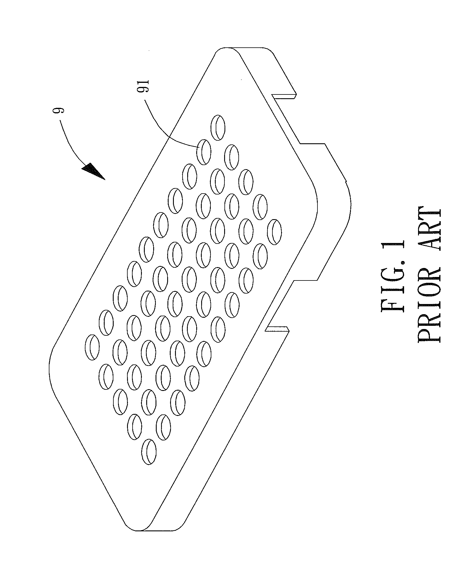
BACKGROUND OF THE INVENTION[0001]1. Field of the Invention[0002]The present invention relates to a protective cover for a hand-held electronic device and, more particularly, to a protective cover with a cooling function for a hand-held electronic device.[0003]2. Description of the Related Art[0004]With reference to FIG. 1, a conventional protective cover 9 for a hand-held electronic device generally includes an inner, protective layer on an inner face thereof and an outer, ornamental layer on an outer face thereof. When the protective cover 9 is mounted to an outer side of a hand-held electronic device, the inner, protective layer prevents the hand-held electronic device from scratch during normal use and provides protection if the hand-held electronic device falls by accident or is impacted, reducing breakage and damage of the screen and reducing deformation of the casing of the hand-held electronic device. Furthermore, the outer, ornamental layer of the protective cover 9 can incl...

Claims


Application Information

Patent Timeline
IPC IPC(8): H05K7/20
CPCH05K7/20136H05K7/20145A45C11/00G06F1/1628G06F1/203H04B1/3888A45C2011/002H05K7/20163
Inventor LI, MING-TSUNGLIN, SHIH-HANG
Owner SUNON ELECTRONICS FOSHAN
Learn More