Optical recording method and medium

Inactive Publication Date: 2007-03-27
TDK CORPARATION
View PDF20 Cites 7 Cited by
  • Summary
  • Abstract
  • Description
  • Claims
  • Application Information

AI Technical Summary

Benefits of technology

[0049]To enhance the cross-erasing reducing effect according to the invention, the cooling efficiency of the land 2L is preferably increased. To this end, the structure shown in each of FIGS. 3 and 4 should preferably be a rapid cooling structure in which the reflective layer 5 has a thermal conductivity of at least 100 W/mK, and the second dielectric layer 32 between the recording layer 4 and the reflective layer 5 has a thermal conductivity of at least 1 W/mK.
[0050]It is now considered why a track pitch PT smaller than the specific value results in increased cross-erasing despite equivalent PT/(λ/NA). In FIGS. 1 and 2, the recorded marks 4M are in accurate alignment with the grooves 2G or lands 2L. That is, these figures are drawn on the assumption of accurate tracking. However, in an actual process, the tracking servo control will sometimes become unstable, especially at a high linear velocity. If the tracking servo control is unstable, the position of a beam spot fluctuates in a lateral direction in the figures, increasing the likelihood of cross-erasing. The instability of the tracking servo control depends on just the track pitch PT rather than the relative value of the track pitch to the beam spot diameter, PT/(λ/NA). The tracking servo control becomes more unstable at a smaller track pitch PT. As a consequence, even with the setting of PT/(λ/NA) equal to DVD-RW, noticeable cross-erasing occurs when PT is smaller than that of DVD-RW. It is noted that the present invention is effective particularly when the linear velocity is so high that the tracking servo control may become unstable, and specifically when the linear velocity V of the medium is V≧4.5 m/s, and especially V≧5.5 m/s. Since too high a linear velocity gives rise to the problems of the increased cost of a medium driving unit and unstable driving of the medium, the linear velocity V is preferably 35 m/s≧V, and especially 30 m/s≧V.
[0051]When the track pitch PT is large and/or when the linear velocity is low, the likelihood of cross-erasing caused by a tracking servo failure

Problems solved by technology

At too high a crystallization speed, amorphous recorded marks become unstable due to the enhanced

Method used


Image

  • Optical recording method and medium
  • Optical recording method and medium
  • Optical recording method and medium

Examples


Example

EXAMPLE

[0088]Examples of the invention are given below by way of illustration and not by way of limitation.

Example

Example 1

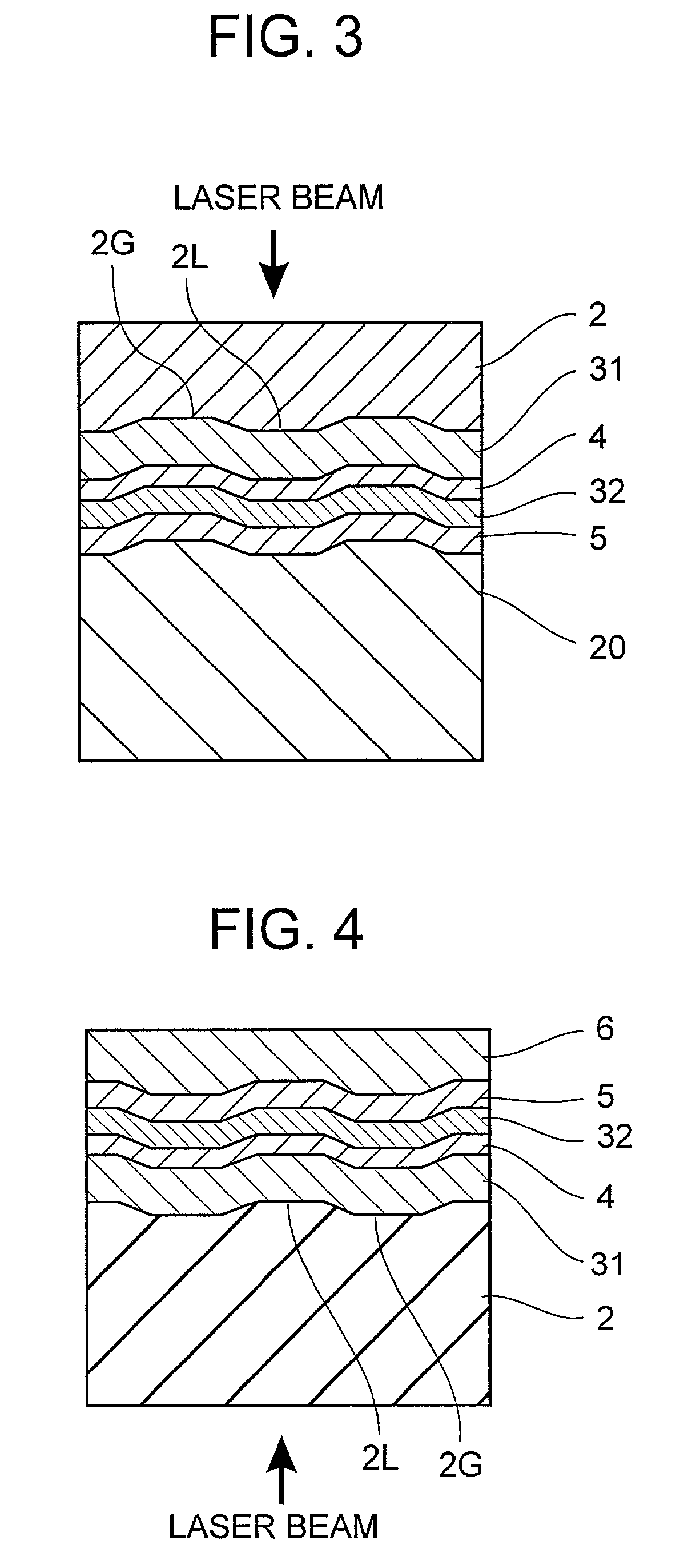
[0089]Optical recording disk samples of the structure illustrated in FIG. 3, capable of recording in the groove or land / groove recording mode, were prepared by the following procedure.

[0090]The supporting substrate 20 used was formed by molding polycarbonate into a disk having a diameter of 120 mm and a thickness of 1.2 mm. The supporting substrate was provided on its surface with a recess and protrusion pattern which would form grooves and lands in a light-transparent substrate 2 after transfer.

[0091]The reflective layer 5 was formed by sputtering in an Ar atmosphere. The target used was Ag98Pd1Cu1. The reflective layer was 100 nm thick and had a thermal conductivity of 170 W / mK.

[0092]The second dielectric layer 32 was formed by sputtering an Al2O3 target in an Ar atmosphere. The second dielectric layer was 20 nm thick. The Al2O3 used as the target had a thermal conductivity of 10.5 W / mK.

[0093]The recording layer 4 was formed by sputtering an alloy target in an Ar atmosph...

Example

Example 2

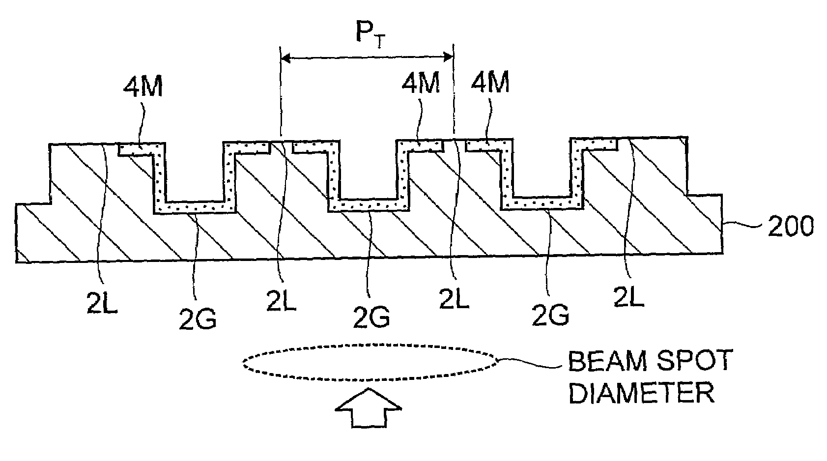
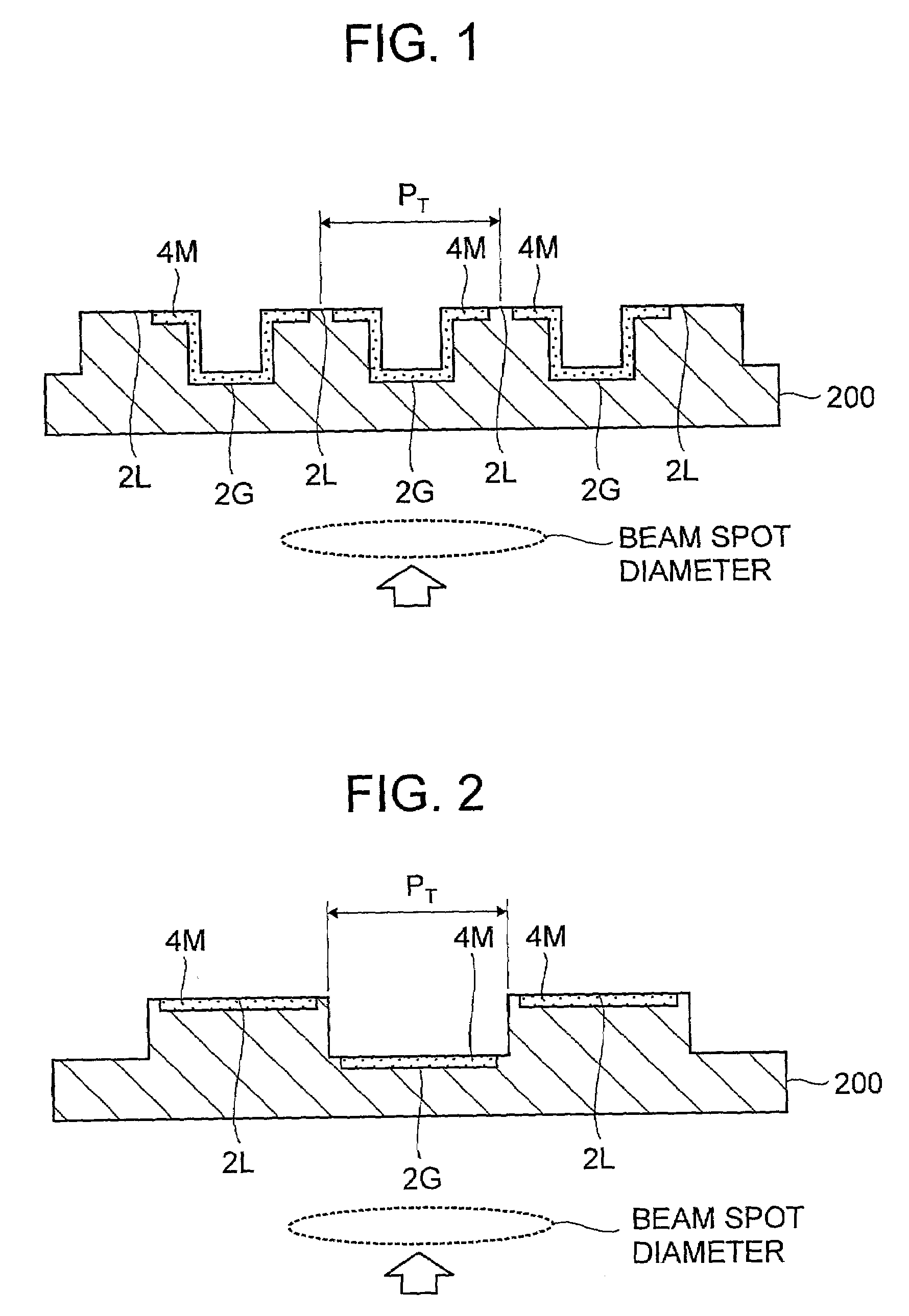
[0110]Optical recording disk samples were fabricated as in Example 1 except that a supporting substrate 20 having a high dimensional precision in groove width was used and the track pitch PT was as shown in Table 2. It is noted that PT in Table 2 is not the imaginary track pitch in Example 1, but an actual track pitch.

[0111]These samples were evaluated as in Example 1. The results are shown in Table 2. After recording in each sample according to the groove recording mode, a photomicrograph of the recording layer was taken through a transmission electron microscope. From the photomicrograph, the recorded mark width Mw was determined, and its ratio to groove width Gw and its ratio to track pitch PT were calculated. As a result, Mw / Gw was in the range between 2.0 and 2.8, and Mw / PT was in the range between 0.70 and 0.86.

[0112]TABLE 2λ = 405 nm, NA = 0.85Cross-erasing (dB)GrooveLand / groovePTPT / recordingrecording(μm)(λ / NA)G-XEG-XEL-XE0.330.6930−0.700.300.6300−1.100.280.5880−2.6...


PUM


Abstract

In an optical recording medium including a grooved light-transparent substrate, a phase change recording layer, a dielectric layer and a reflective layer, recording is carried out by irradiating a laser beam to the recording layer through an objective lens in an optical system. The recording is carried out in a groove recording mode under the conditions: 0.48≦PT/(λ/NA)≦0.74, and PT≦0.50 μm wherein λ is a laser beam wavelength, NA is an objective lens numerical aperture, and PT is a track pitch, thereby forming a recorded mark having opposite ends extending out of the groove. This enables high density recording and increases the data transfer rate of a phase change optical recording medium.

Description

[0001]This invention relates to an optical recording method and a phase change optical recording medium.BACKGROUND OF THE INVENTION[0002]Great attention is now paid to optical recording media capable of high density recording and erasing the once recorded information for rewriting. Among such rewritable optical recording media, phase change recording media are designed such that recording is performed by irradiating a laser beam to the recording layer to change its crystalline state and reading is performed by detecting the change of reflectivity of the recording layer associated with that state change. The phase change recording media are of greater interest because modulating the intensity of a single laser beam enables overwriting and the drive unit used for their operation may have a simple optical system as compared with that used for magneto-optical recording media.[0003]For the phase change recording layer, chalcogenide materials such as Ge—Te and Ge—Sb—Te base materials are ...

Claims


Application Information

Patent Timeline
IPC IPC(8): G11B7/24G11B7/004G11B7/0045G11B7/006G11B7/007G11B7/24079G11B7/243G11B7/256G11B7/2578G11B7/258
CPCG11B7/00454G11B7/006G11B7/24079G11B7/243G11B7/00718G11B2007/24316G11B7/2578G11B7/258G11B2007/2431G11B2007/24312G11B2007/24314G11B7/256G11B7/004
Inventor KATO, TATSUYAHIRATA, HIDEKIUTSUNOMIYA, HAJIMEINOUE, HIROYASU
Owner TDK CORPARATION
Why Eureka
Try Eureka