Amphibious vehicle

Active Publication Date: 2017-08-24
LIVERPOOL CITY SIGHTS LTD
View PDF6 Cites 2 Cited by
  • Summary
  • Abstract
  • Description
  • Claims
  • Application Information

AI Technical Summary

Benefits of technology

[0083]Advantageously, the fans are controllable to be non operable when the amphibious vehicle is in the water. In this way, all available power produced by the engine can be directed to the water propulsion system.
[0084]Conveniently, the location of the one or more radiators within the rear wheel wells of the amphibious vehicle, i.e. spaced apart from the engine, means that when on land the ambient air which cools the radiators will not be preheated by passing over the engine, exhaust, turbo, transmission of the vehicle. In this way, the cooling efficiency of the radiator is increased. In addition, the heat dissipation along the increased length of the piping between the engine and radiator assists in cooling the engine coolant, particularly where the piping runs external to the hull.
[0085]Advantageously also,

Problems solved by technology

However these vehicles are becoming increasingly obsolete due to outdated technologies.
While many operators continue their attempts to modify the original DUKW design, it is becoming increasingly difficult and uneconomical to do so while complying with the essential regulatory standards for operation.
In particular, it has been a great challenge to upgrade the existing DUKW design to meet the United Kingdom regulations for buoyancy res

Method used


Image

  • Amphibious vehicle
  • Amphibious vehicle
  • Amphibious vehicle

Examples


Example

[0093]Embodiments of the present invention will now be described, by way of example only, with reference to the accompanying drawings in which:

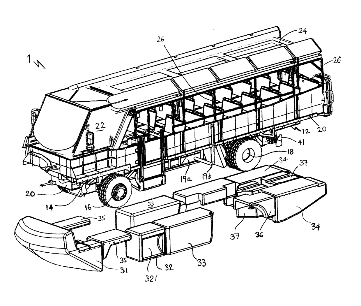
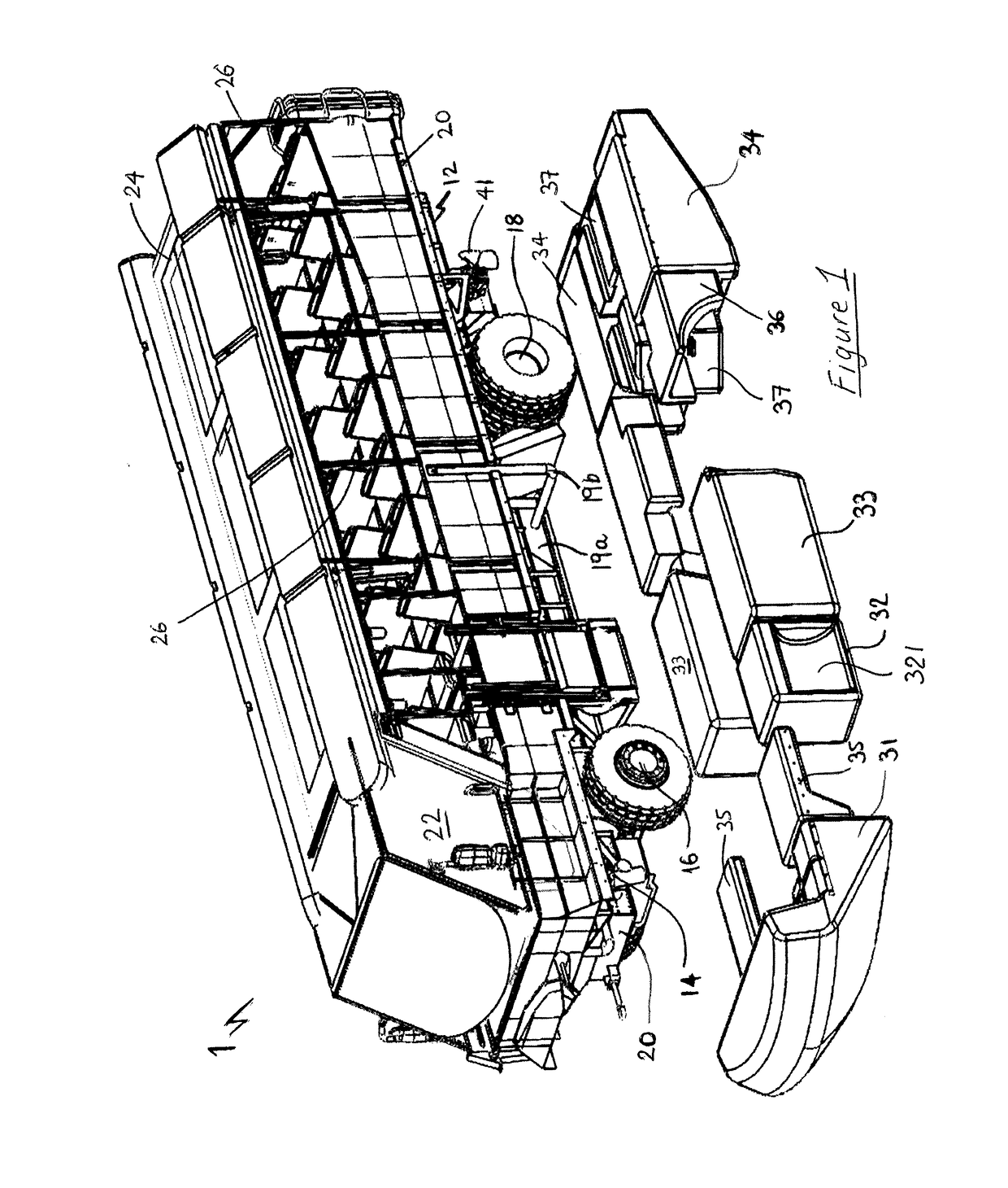
[0094]FIG. 1 is a schematic perspective illustration of an exemplary amphibious vehicle in accordance with the invention and showing exemplary buoyancy modules separated from the vehicle;

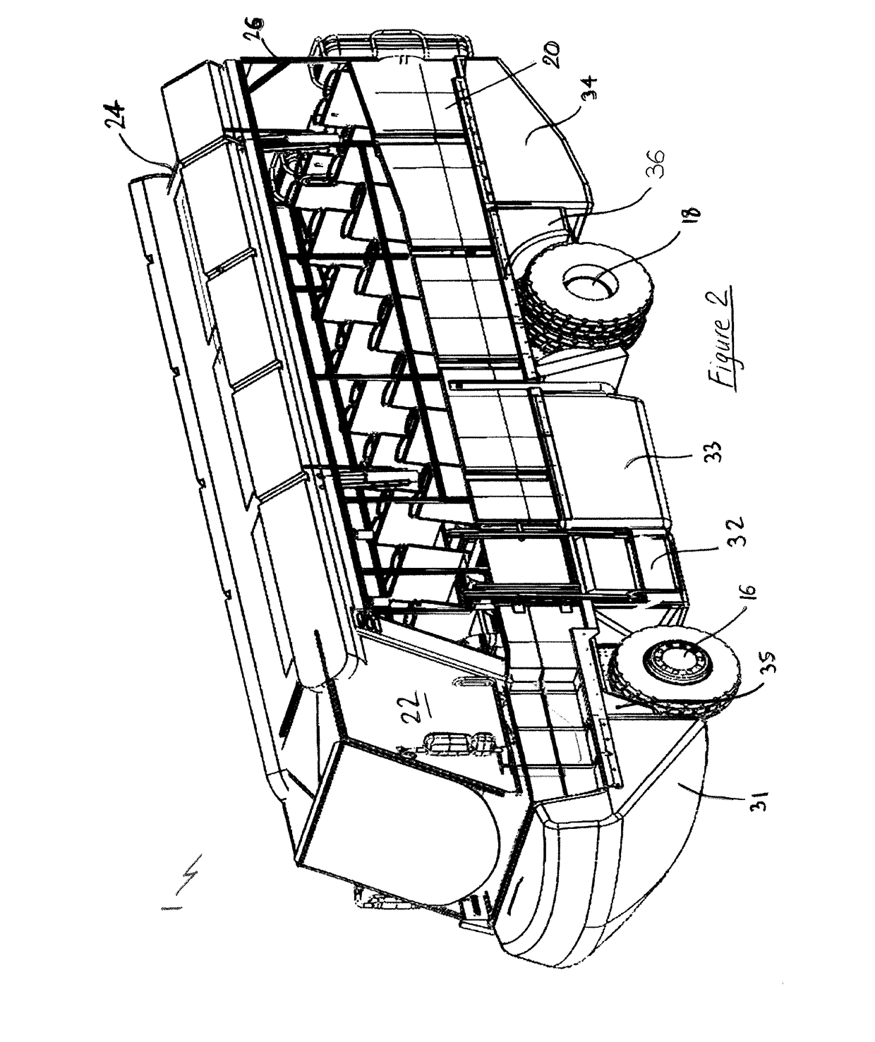
[0095]FIG. 2 is a schematic perspective illustration of the amphibious vehicle of FIG. 1 showing exemplary buoyancy modules mounted to the vehicle;

[0096]FIG. 3 is a schematic perspective illustration showing the underside and rear of the amphibious vehicle of FIG. 1 and in which the engine cooling system and water propulsion system is visible;

[0097]FIG. 4 is a schematic illustration showing an engine cooling system and water propulsion system in accordance with the invention;

[0098]FIG. 5 is a detailed view of the water propulsion system shown in FIG. 4;

[0099]FIGS. 6 and 7 are schematic perspective illustrations of a hull of the amphibious vehicle in accordanc...


PUM


Abstract

An improved amphibious vehicle comprising: a drive train; a plurality of ground engaging wheels; a cooling system; a water propulsion system; and a hull which defines a passenger compartment, wherein the form/shape of the hull below the waterline is substantially defined by a plurality of buoyancy modules that are demountably mountable to the amphibious vehicle.

Description

[0001]The present invention relates to an amphibious vehicle and a propulsion and cooling system therefor, in particular to an improved amphibious vehicle particularly adapted for sightseeing services.BACKGROUND OF THE INVENTION[0002]Self propelled vehicles having ground engaging wheels and being capable of operation on both land and in water are well known in the art. Such vehicles are most often seen nowadays as sightseeing vehicles whereby vehicle passengers visit sights on land before the vehicle enters the water as part of the sightseeing experience. Many of these sightseeing amphibious vehicles are based on the original GMC DUKWs from the early 1940s. However these vehicles are becoming increasingly obsolete due to outdated technologies. While many operators continue their attempts to modify the original DUKW design, it is becoming increasingly difficult and uneconomical to do so while complying with the essential regulatory standards for operation. In particular, it has been ...

Claims


Application Information

Patent Timeline
IPC IPC(8): B60F3/00B63H21/38B63H5/125
CPCB60F3/0038B60F3/0007B63H2005/1254B63H5/125B63H21/38B60F3/0069B60F3/0053B63H21/165
Inventor THOMPSON, IAN GEORGE MERVYNMCDOWELL, ROBERT FLINTBARR, STEVENCOLHOUN, ANDREW
Owner LIVERPOOL CITY SIGHTS LTD
Why Eureka
Try Eureka