

Heat dissipating device
- Summary
- Abstract
- Description
- Claims
- Application Information
AI Technical Summary
Benefits of technology
Problems solved by technology
Method used
Image

Examples
Embodiment Construction
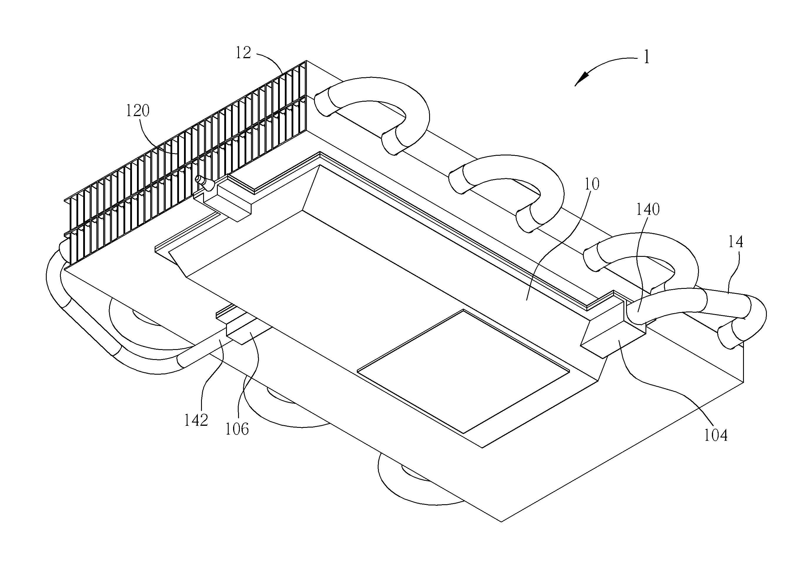
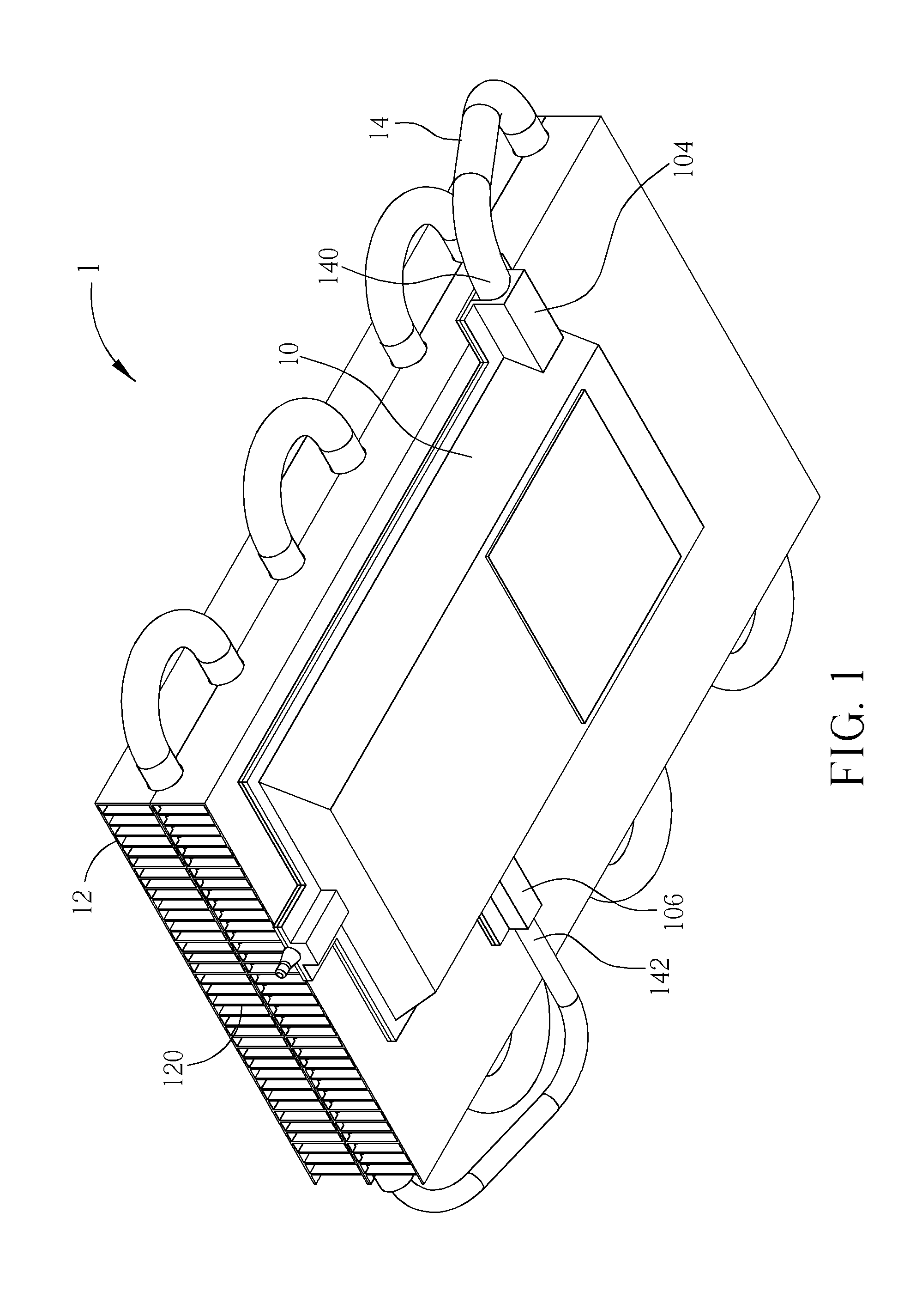
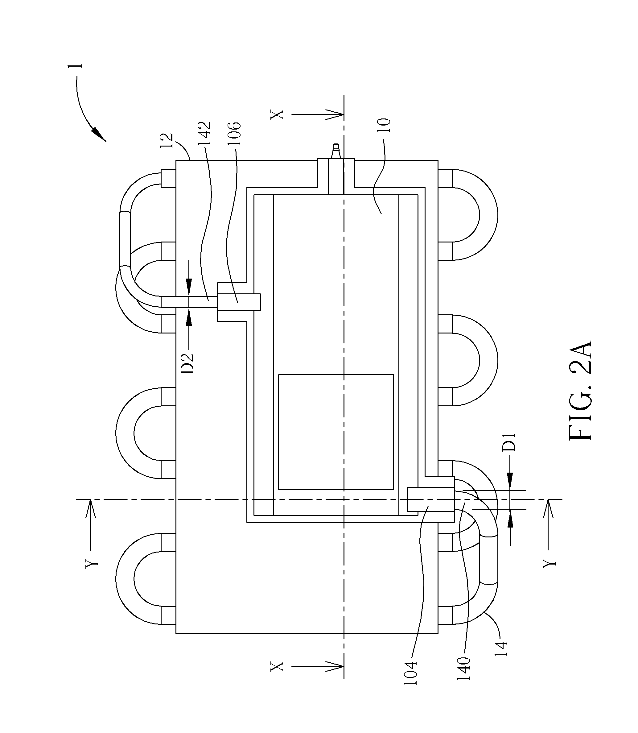
[0022]Referring to FIGS. 1 to 3, FIG. 1 is a perspective view illustrating a heat dissipating device 1 according to an embodiment of the invention, FIG. 2A is a top view illustrating the heat dissipating device 1 shown in FIG. 1, FIG. 2B is cross-sectional view illustrating the heat dissipating device 1 along X-X line shown in FIG. 2A, FIG. 2C is a cross-sectional view illustrating the heat dissipating device 1 along Y-Y line shown in FIG. 2A, and FIG. 3 is an assembly view illustrating the chamber body 10 and the first capillary structure 16 shown in FIG. 2B from different view angles.
[0023]As shown in FIGS. 1 to 3, the heat dissipating device 3 comprises a chamber body 10, a heat sink 12, a pipe 14, a first capillary structure 16, N vapor channels 18 and a vapor collecting space 20, wherein N is a positive integer. The chamber body 10 has an evaporation chamber 100 and a compensation chamber 102, wherein the evaporation chamber 100 has a vapor outlet 104 and the compensation chamb...
PUM
 Abstract
Description
Claims
Application Information