Electrical connector structure

Active Publication Date: 2017-08-22
ALL BEST PRECISION TECH
View PDF1 Cites 0 Cited by
  • Summary
  • Abstract
  • Description
  • Claims
  • Application Information

AI Technical Summary

Benefits of technology

[0019]In summary, the present invention utilizes the restraining component connected between the housing and the heat dissipating component of the electrical connector structure, so as to fix the heat dissipating component on the housing and restrain movement of the heat dissipating co

Problems solved by technology

However, in order to satisfy requirements of the high frequency transmission and the lightweight design, contacts and wires per unit area inside the electrical connector become more and more concentrated, which increases the generated heat sharply and raises an operational temperature inside of the electrical connector when the electrical connector is in operation.
It affects operational function of the electrical connector when the operational temperature is over a normal range of a design temperature, which i

Method used


Image

  • Electrical connector structure
  • Electrical connector structure
  • Electrical connector structure

Examples


Example

[0030]In order to illustrate technical specifications and structural features as well as achieved purposes and effects of the present invention, relevant embodiments and figures are described as follows.

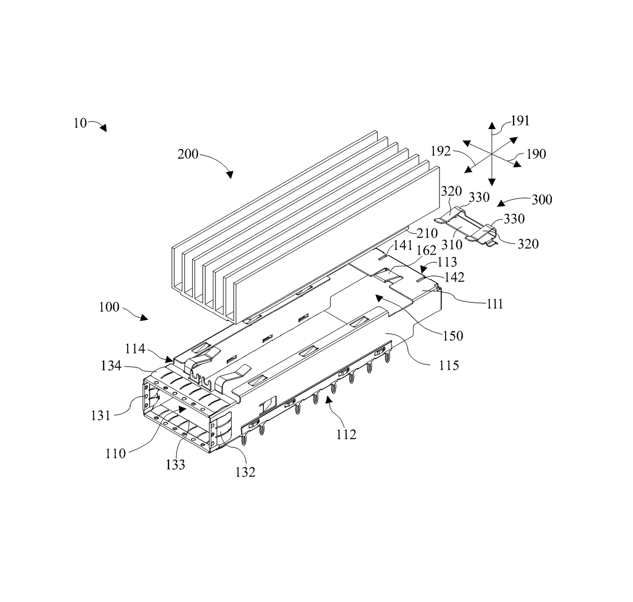
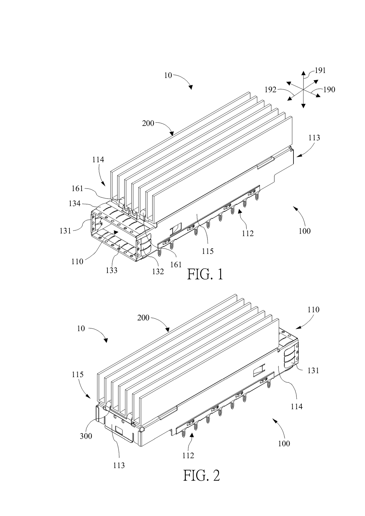
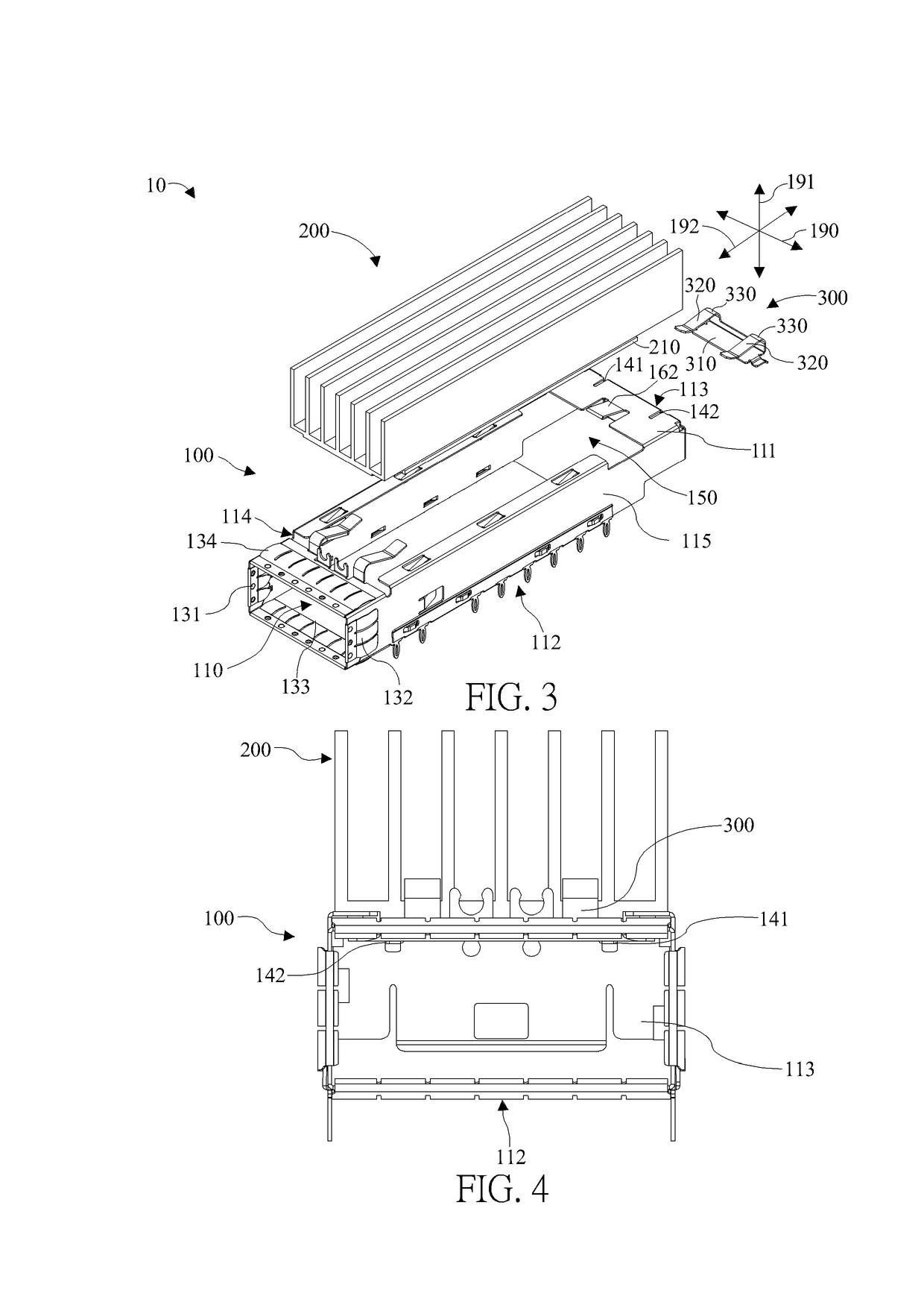
[0031]Please refer to FIG. 1 to FIG. 3. FIG. 1 is a schematic diagram of an electrical connector structure 10 according to an embodiment of the present invention. FIG. 2 is a schematic diagram of the electrical connector structure 10 at another view according to the embodiment of the present invention. FIG. 3 is an exploded diagram of the electrical connector structure 10 according to the embodiment of the present invention. As shown in FIG. 1 to FIG. 3, the electrical connector structure 10 is electrically disposed on a printed circuit board, which is not shown in figures, and adapted for a plug module, which is not shown in figures.

[0032]The electrical connector structure 10 includes a housing 100, a heat dissipating component 200, and a restraining component 300. The housing 100 m...


PUM


Abstract

An electrical connector structure adapted for a plug module includes a housing, a heat dissipating component, and a restraining component. The housing includes a top wall whereon a top opening is formed. The heat dissipating component is disposed above the top opening. The restraining component includes a first restraining segment, a second restraining segment, a bending segment, a pressing portion, and an extending element. The pressing portion is connected to the second restraining segment. The bending segment is connected between the first restraining segment and the second restraining segment. The extending element is coupled to the housing, and the pressing portion is coupled to the heat dissipating component, so as to cooperatively fix the heat dissipating component above the top opening. Therefore, the heat dissipating component can be closely attached on the plug module inside the housing at all times to enhance heat dissipating efficiency.

Description

BACKGROUND OF THE INVENTION[0001]1. Field of the Invention[0002]The present invention relates to an electrical connector structure, and more particularly, to an electrical connector structure having a heat dissipating component and a restraining component with simple structure, easy assembly, and an enhanced holding effect.[0003]2. Description of the Prior Art[0004]With rapid development of electronic industries and communication equipment, there are more and more standards for electrical connectors released. The current trend is towards to high frequency transmission and lightweight design. However, in order to satisfy requirements of the high frequency transmission and the lightweight design, contacts and wires per unit area inside the electrical connector become more and more concentrated, which increases the generated heat sharply and raises an operational temperature inside of the electrical connector when the electrical connector is in operation. It affects operational functio...

Claims


Application Information

Patent Timeline
IPC IPC(8): H05K7/20H01R12/58
CPCH05K7/20409H01R12/585H01R13/6582
Inventor YANG, HAVEN
Owner ALL BEST PRECISION TECH
Why Eureka
Try Eureka