Complex heat dissipation assembly for backlight module

Inactive Publication Date: 2014-12-18
WU CHE YUAN
View PDF0 Cites 3 Cited by
  • Summary
  • Abstract
  • Description
  • Claims
  • Application Information

AI Technical Summary

Benefits of technology

[0006]It is therefore a primary object of the present invention to provide a complex heat dissipation assembly for backlight module, which is able to quickly outward dissipate t

Problems solved by technology

As a result, the heat generated by the light sources will inevitably increase.
Otherwise, the heat will accumulate around the light sources to cause abnormal rise of the temperature of a local part of the periphery of the (liquid crystal) screen.
This not only will affect the function of the electronic product, but also will shorten the lifetime of the relevant components.
However, th

Method used


Image

  • Complex heat dissipation assembly for backlight module
  • Complex heat dissipation assembly for backlight module
  • Complex heat dissipation assembly for backlight module

Examples


Example

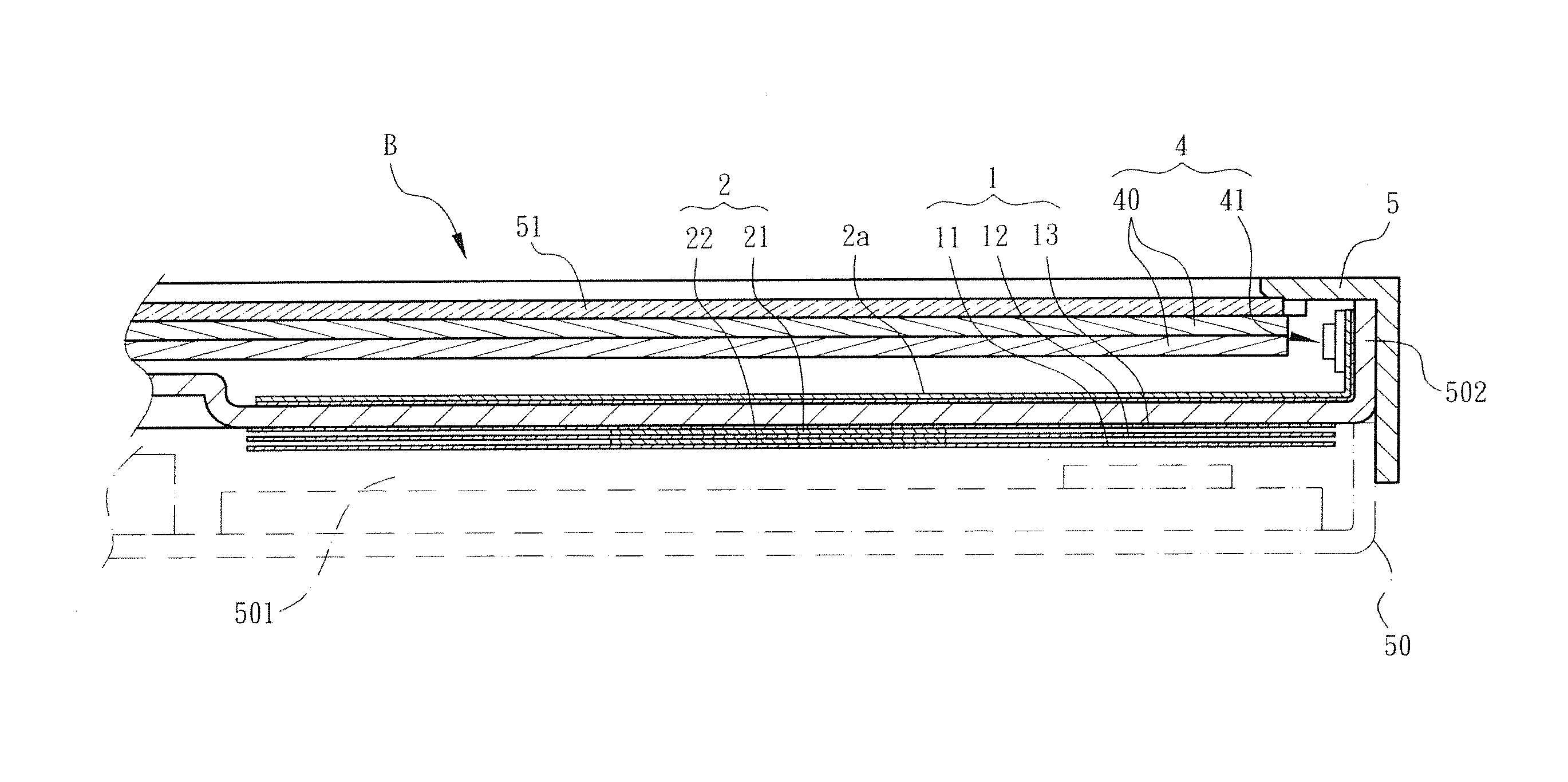
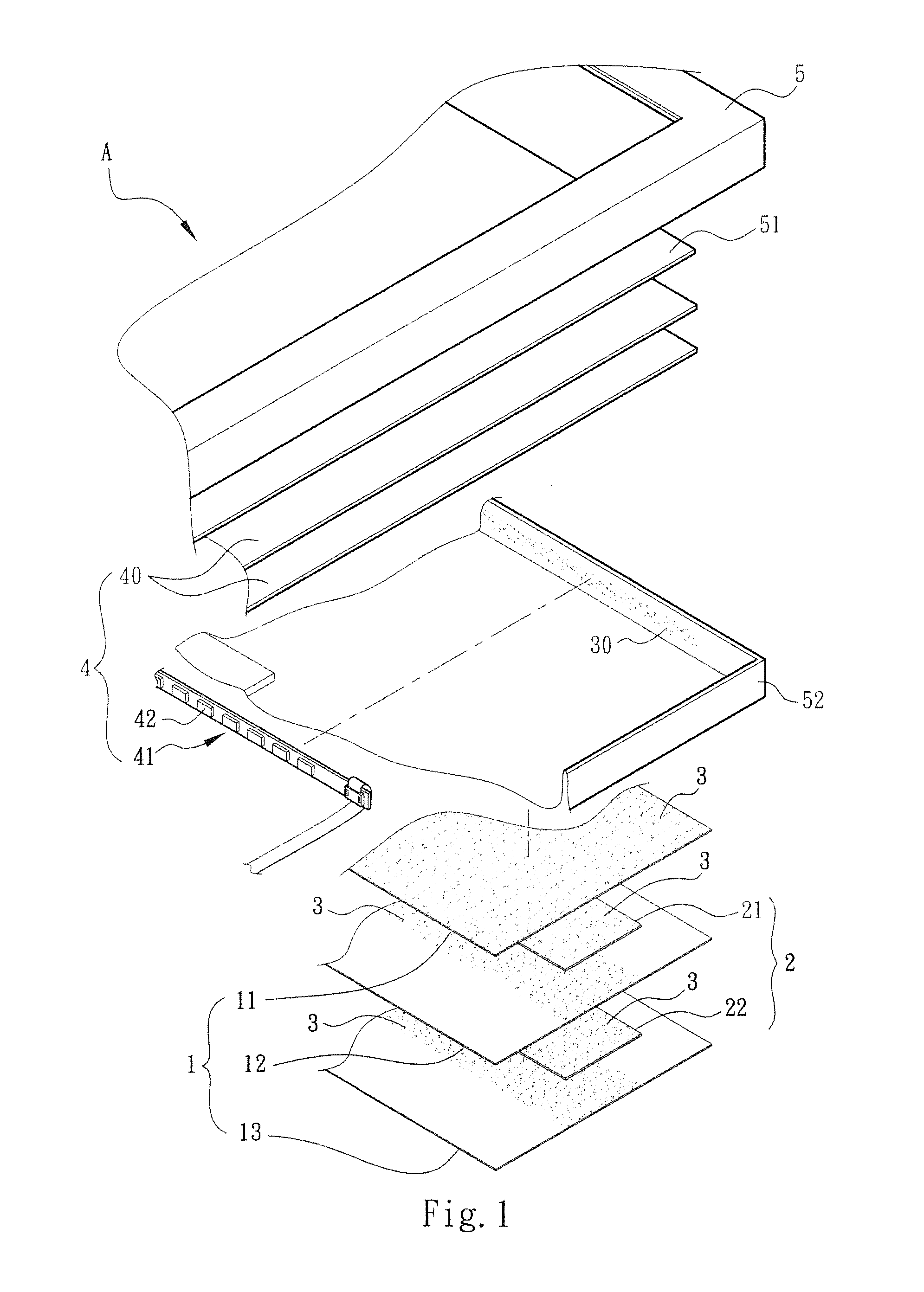
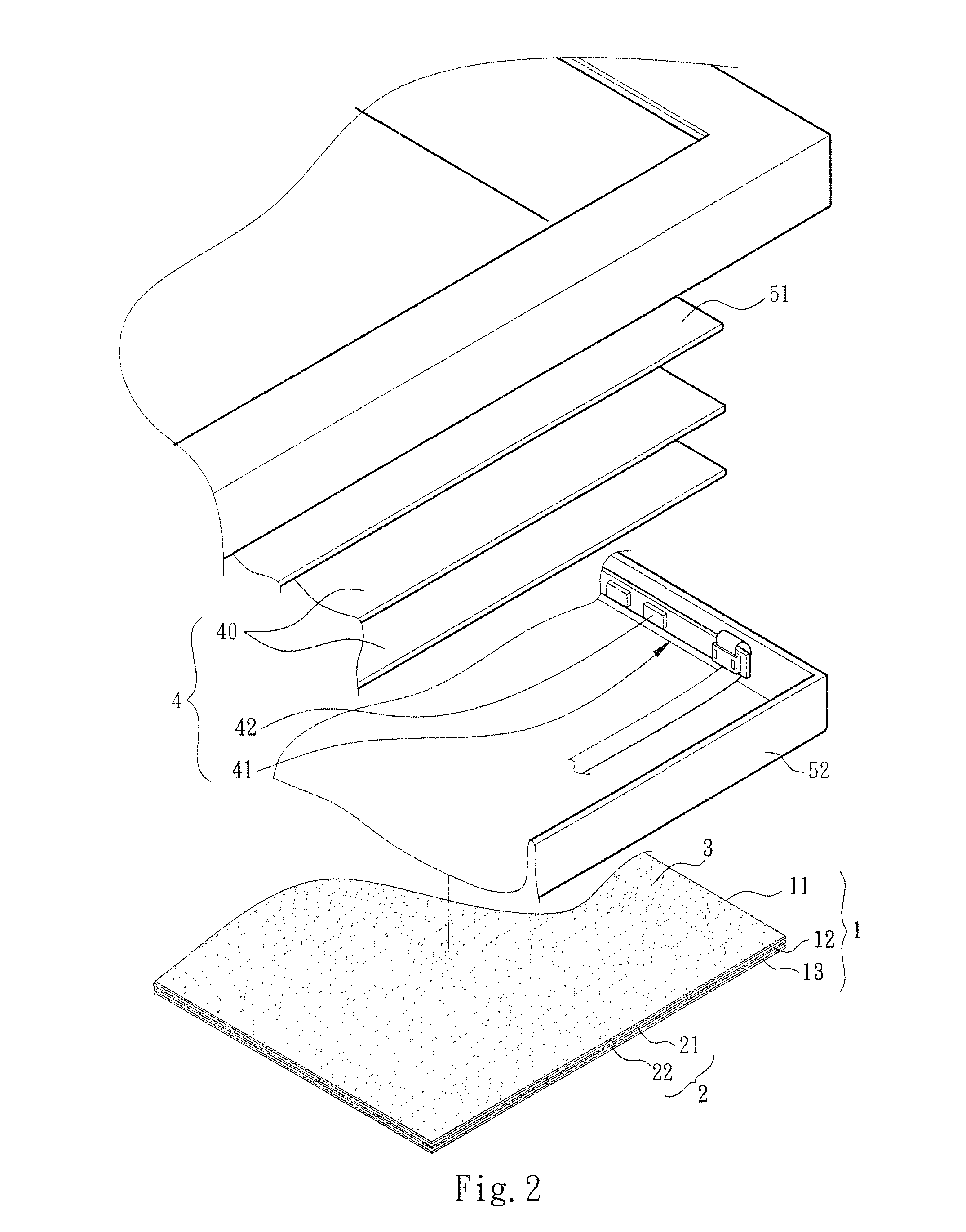
[0029]Please refer to FIGS. 1 to 3. According to a first embodiment, the complex heat dissipation assembly for backlight module of the present invention includes a heat conduction plate assembly 1 and a heat spreader assembly 2. The heat conduction plate assembly 1 is composed of multiple sequentially stacked electroconductive heat conduction plates 11, 12, 13, (which can be made of metal material). The heat spreader assembly 2 is composed of multiple heat spreaders 21, 22 respectively alternately disposed between the heat conduction plates 11, 12, 13. The heat spreaders 21, 22 have an area smaller than that of the heat conduction plates 11, 12, 13. The heat spreaders 21, 22 can be made of graphite or the like material. The heat spreaders 21, 22 have a property of quickly conducting heat along the surface (transversely), whereby the heat will not easily directly penetrate through the heat spreaders 21, 22. In this embodiment, the heat spreaders 21, 22 are elongated plate bodies. The...

Example

[0033]Please refer to FIG. 4. According to a second embodiment, the complex heat dissipation assembly for backlight module of the present invention includes a heat spreader assembly 20 and a heat conduction plate assembly 1 identical to that of the first embodiment. The heat conduction plate assembly 1 identically includes multiple heat conduction plates 11, 12, 13. The heat spreader assembly 20 is composed of multiple heat spreaders 201, 202 respectively alternately disposed between the heat conduction plates 11, 12, 13. The heat spreaders 201, 202 have an area equal to that of the heat conduction plates 11, 12, 13. The heat spreaders 201, 202 can be made of graphite or the like material. The heat spreaders 201, 202 have a property of quickly conducting heat along the surface (transversely), whereby the heat will not easily directly penetrate through the heat spreaders 201, 202. The heat spreaders 201, 202 and the heat conduction plates 11, 12, 13 are electrically bonded to each ot...

Example

[0035]Please refer to FIG. 5. According to a third embodiment, the complex heat dissipation assembly for backlight module of the present invention includes a heat spreader assembly 6 and a heat conduction plate assembly 1 identical to that of the first embodiment. The heat conduction plate assembly 1 identically includes multiple heat conduction plates 11, 12, 13. The heat spreader assembly 6 is composed of multiple heat spreaders 61, 62 respectively alternately disposed between the heat conduction plates 11, 12, 13. The heat spreaders 61, 62 have an area smaller than that of the heat conduction plate assembly 1. The heat spreaders 61, 62 can be made of graphite or the like material. The heat spreaders 61, 62 have a property of quickly conducting heat along the surface (transversely). In this embodiment, each of the heat spreaders 61, 62 has multiple branch sections 612, 622 obliquely extending from one side of the heat spreader 61, 62 in parallel to each other. The heat spreaders 6...


PUM


Abstract

A complex heat dissipation assembly for backlight module, which is applicable to the backlight module of a screen of an electronic product for dissipating heat. The complex heat dissipation assembly includes: a heat conduction plate assembly composed of multiple electroconductive heat conduction plates, the heat conduction plate assembly being disposed on a rear surface of the backlight module; and a heat spreader assembly composed of multiple heat spreaders, which are able to quickly transversely conduct heat. The heat spreaders are disposed between the heat conduction plates in contact therewith. The heat conduction plate assembly and the heat spreader assembly cooperate with each other to complexly conduct and spread the heat generated by the backlight module in different directions so as to prevent the heat from accumulating around the backlight module. In this case, the temperature will not locally abnormally rise.

Description

BACKGROUND OF THE INVENTION[0001]1. Field of the Invention[0002]The present invention relates generally to a complex heat dissipation assembly for backlight module, and more particularly to a low-cost and simple-structure heat conduction structure, which is able to quickly and uniformly dissipate the heat generated by the backlight module so as to avoid accumulation of the heat in a narrow space.[0003]2. Description of the Related Art[0004]The conventional backlight module applied to the (liquid crystal) screen of an electronic product basically includes at least one light guide plate and multiple light sources arranged on a part of the periphery of the light guide plate. (The light sources are generally cold-cathode tubes or light-emitting diodes). The light guide plate serves to uniformly spread the light emitted from the light sources to form a backlight beam as a face light source. Along with the gradual enlargement of the size of the (liquid crystal) screen, the number of the l...

Claims


Application Information

Patent Timeline
IPC IPC(8): F21V29/00
CPCF21V29/004G02B6/0085G02F1/133628
Inventor WU, CHE YUAN
Owner WU CHE YUAN
Why Eureka
Try Eureka