Furnace blower with double sided impeller

Inactive Publication Date: 2001-11-20
JAKEL MOTORS
View PDF14 Cites 48 Cited by
  • Summary
  • Abstract
  • Description
  • Claims
  • Application Information

AI Technical Summary

Problems solved by technology

During operation of the furnace, temperatures in the vestibule increase and tend to degrade performance of furnace components located in the vestibule.
The elevated temperature within the vestibule tends to shorten the life of the blower motor, and electronics and controls located within the vestibule.
First, the use of an auxiliary fan on the blower motor increases the size and/or height of the motor a

Method used


Image

  • Furnace blower with double sided impeller
  • Furnace blower with double sided impeller
  • Furnace blower with double sided impeller

Examples


Embodiment Construction

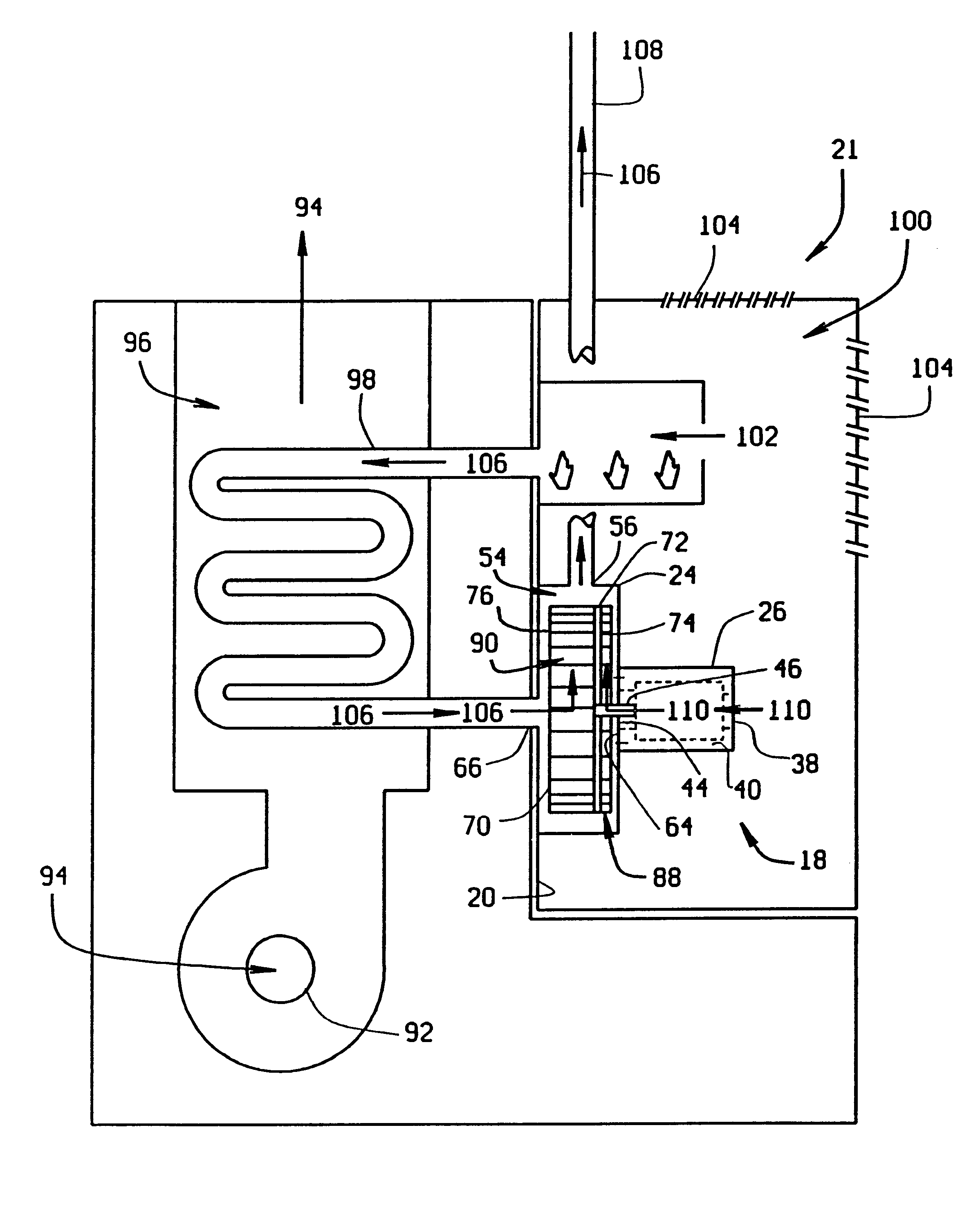
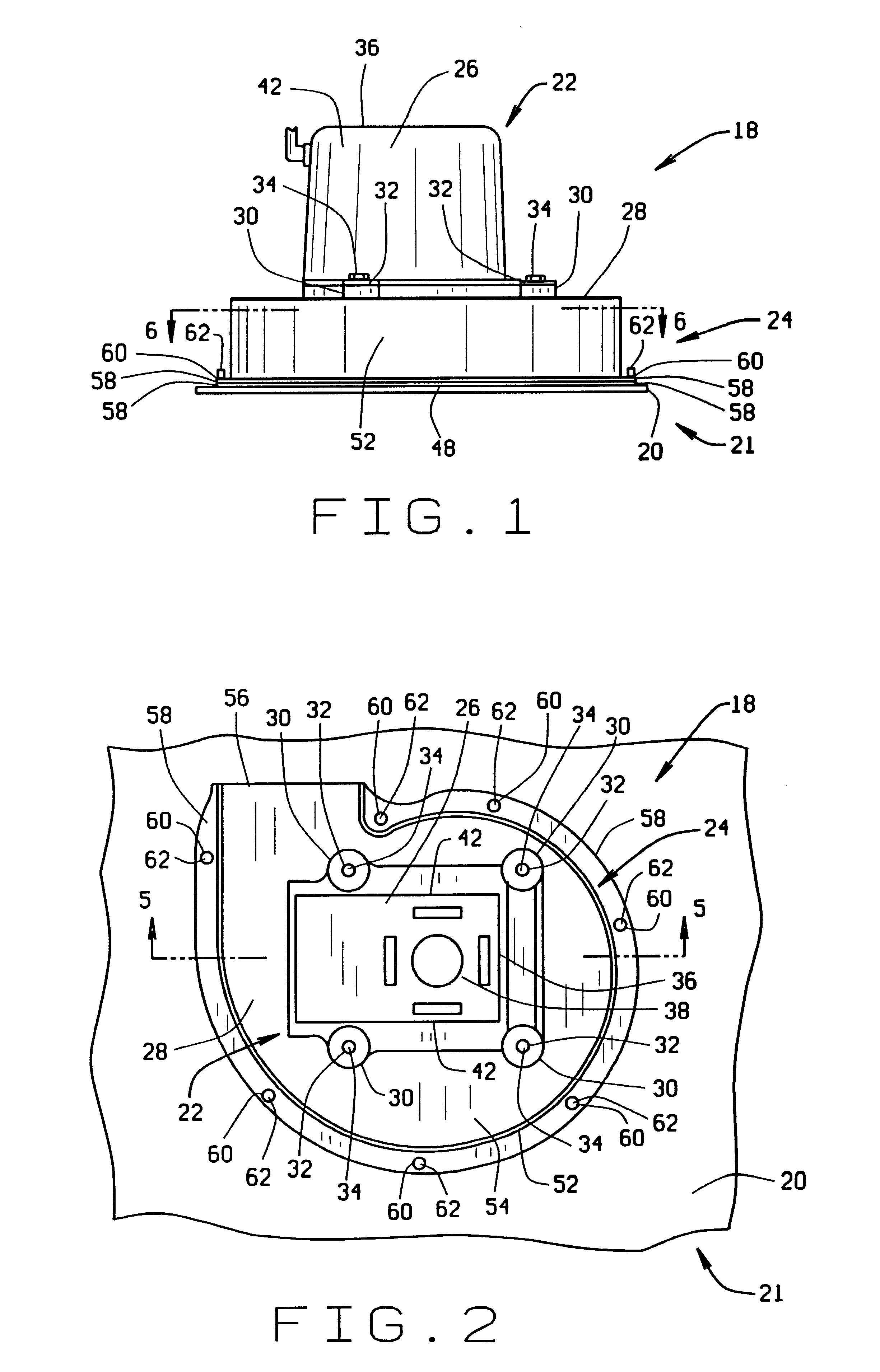
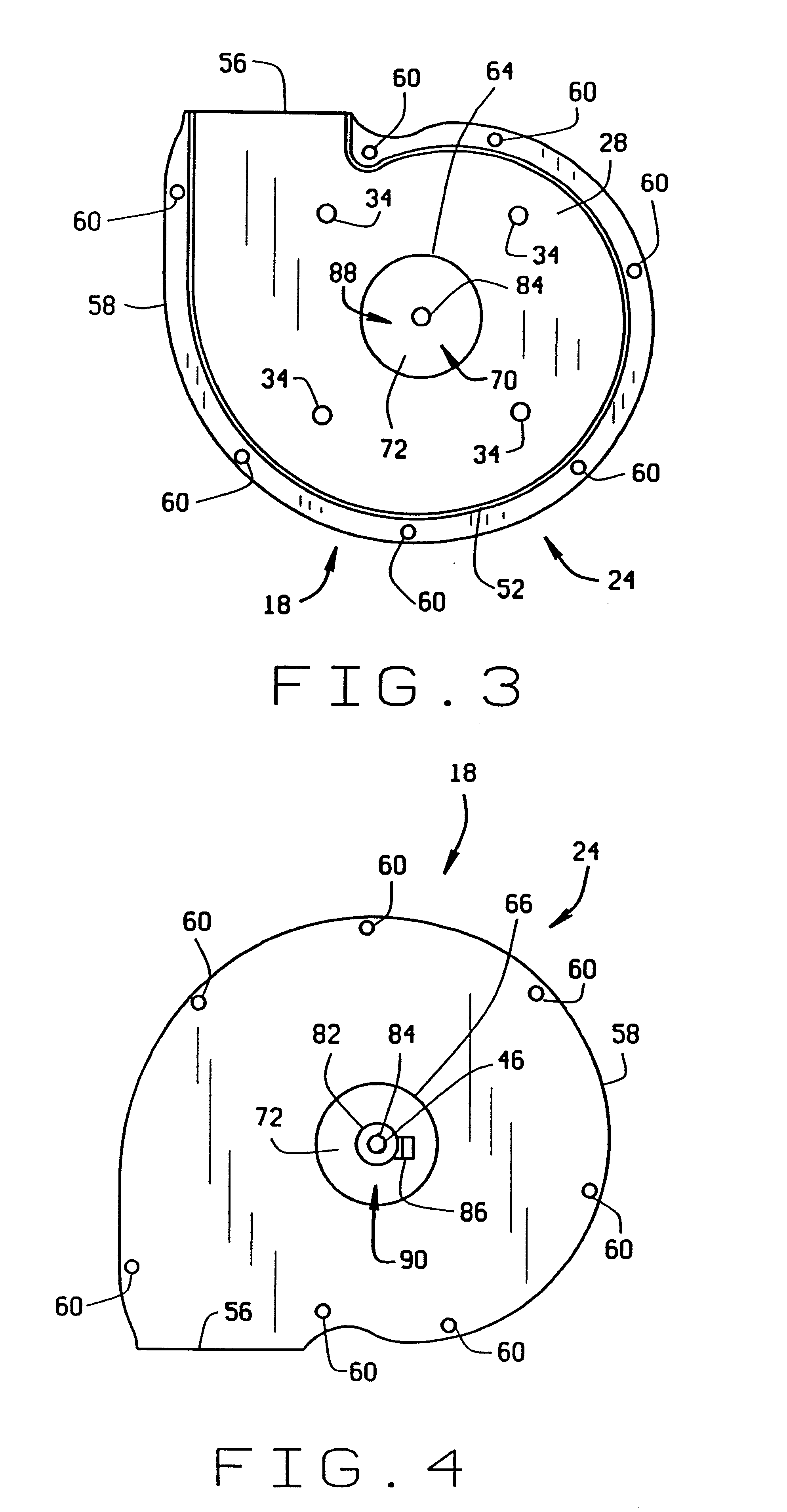
FIGS. 1-6 provide details of the furnace blower 18 of the present invention. The blower 18 is positioned on a blower mounting surface 20 in a furnace 21 and includes a blower motor 22 and a blower housing 24. The blower motor 22 is preferably positioned on top of the blower housing 24 and contained within a motor casing 26. However, the motor 22 and blower housing 24 could have other relative positions. The motor casing 26 is supported on a first side wall 28 of the blower housing 24 by mounting feet 30 extending outward from the motor casing 26. The mounting feet 30 preferably have mounting holes 32, and mechanical fasteners 34 are directed through the mounting holes 32 to secure the motor casing 26 to the first side wall 28 of the blower housing 24.

As shown in FIG. 2, on a top side 36 of the motor 22 opposite the top, first side wall 28 of the blower housing 24, the motor casing 26 preferably has at least one vent hole 38 through the motor casing 26 that leads into an interior 40 ...


PUM


Abstract

A blower for a furnace is provided where the blower has an impeller that is configured to create a primary air flow of combustion air into the blower housing and a secondary air flow of cooling air through the blower motor. The primary air flow of combustion air into the furnace generates hot exhaust gases for a heat exchanger in the furnace. The secondary air flow cools the blower motor. The secondary air flow is mixed with the hot exhaust gases in the blower housing and cools the exhaust gases before being discharged from the blower housing.

Description

(1) Field of the InventionThis invention relates generally to a draft inducing blower in a furnace, and, more particularly, the invention pertains to an improvement in the blower design that provides internal cooling for a motor that drives the blower.(2) Description of the Related ArtBlowers to which the present invention is directed are common in the art. Generally, these blowers are located downstream of a combustion chamber or combustion tubes in the furnace, depending upon the style of furnace. The blower draws combustion air into the combustion chamber or combustion tubes, where the combustion air is mixed with fuel and ignited to generate heat for the furnace. The heated exhaust gases are then drawn through a heat exchanger by the blower and discharged from the blower to an exhaust pipe that vents to the outside atmosphere.The blower generally includes a blower housing and a blower motor installed on the blower housing. The blower housing typically has a side wall, top piece,...

Claims


Application Information

Patent Timeline
IPC IPC(8): F04D25/08F04D25/02F23L17/00F24H3/02F24H3/06
CPCF04D25/082F23L17/005F24H3/065F04D29/5806
Inventor GATLEY, JR., WILLIAM STUART
Owner JAKEL MOTORS
Why Eureka
Try Eureka