Embedded heat pipe for a conduction cooled circuit card assembly

a technology of conduction cooling and circuit card, which is applied in the direction of indirect heat exchangers, electrical apparatus construction details, lighting and heating apparatus, etc., can solve problems such as card and/or system failure, card failure or system failure, improper operation, etc., to reduce electromagnetic radiation and improve signal integrity

Inactive Publication Date: 2005-01-04
DY 4 SYST
View PDF6 Cites 50 Cited by
  • Summary
  • Abstract
  • Description
  • Claims
  • Application Information

AI Technical Summary

Benefits of technology

Implementation of the heat pipes of the present, invention allows for the placement of high powered components 19 at any desired location on the card 10, including near or at

Problems solved by technology

Movement of the card can cause connections to the card to be broken resulting in card and/or system failure.
The use of multiple circuit cards and high-power or densely packed components can often result in the production of heat which cannot be easily dissipated.
Excess heat will create temperatures above a normal or acceptable operating temperature range with the potential for improper operation, card failure or system failure.
Because of the amount of heat generated by the components, and the closely spaced circuit cards and limitations on the chassis, which may include sea

Method used


Image

  • Embedded heat pipe for a conduction cooled circuit card assembly
  • Embedded heat pipe for a conduction cooled circuit card assembly
  • Embedded heat pipe for a conduction cooled circuit card assembly

Examples


Embodiment Construction

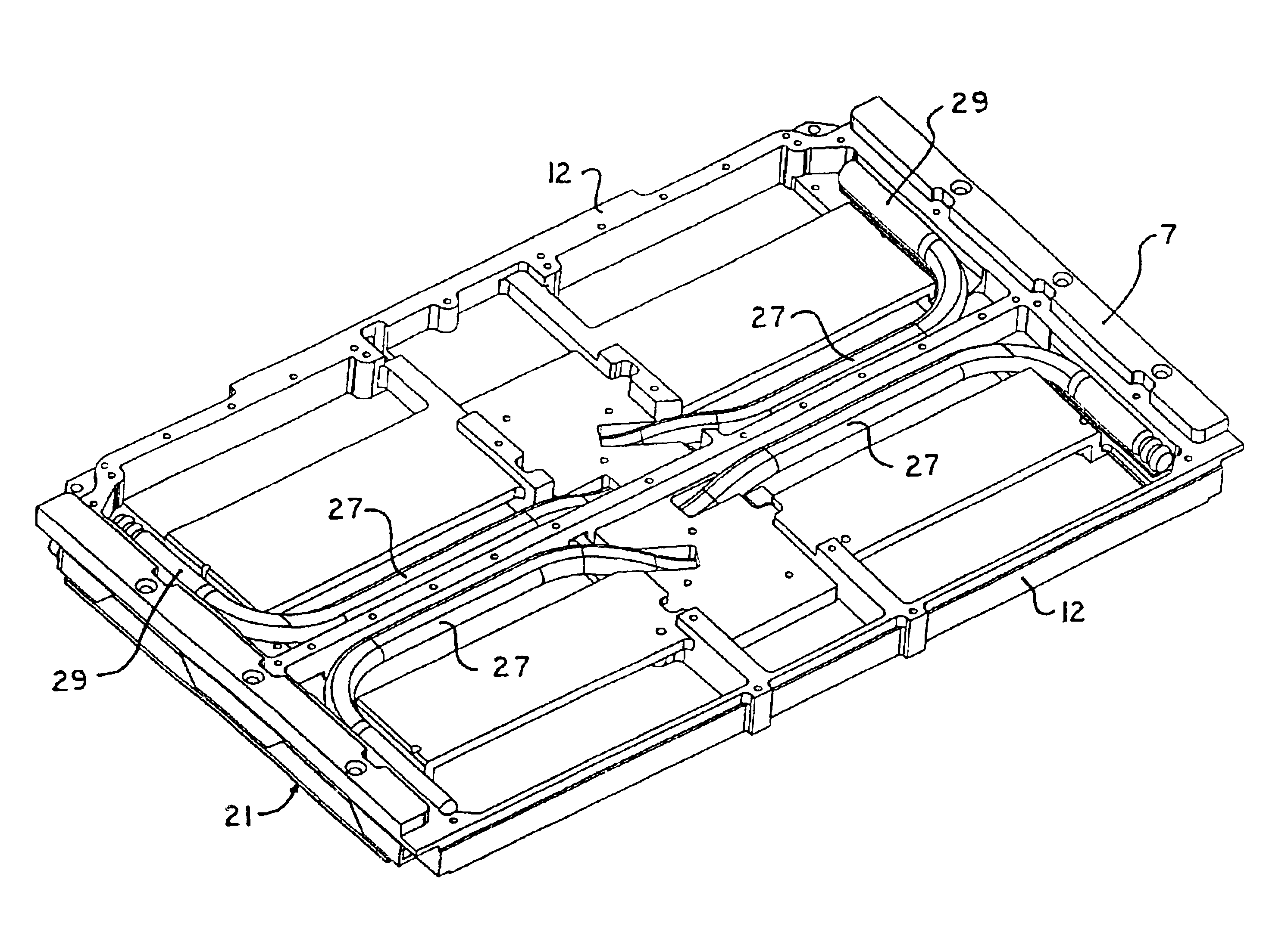
The condenser portion of the heat pipe 29, the area of condensation inside the pipe, is attached to the frame structure along the card edge. A bonding agent, such as tin-lead solder or another thermally conductive adhesive, is used to adjoin the two components, the heat tube condensation end 29 and the end of the frame 12. The opposite end of the heat pipe, the evaporator portion 31 (area of evaporation inside the pipe), is embedded within a heat spreader 26 also referred to as the collector 26. Elements 26 and 31 are better illustrated in FIG. 7.

The collector 26 can also house a second heat pipe 27 that extends to the opposite edge of the frame 12. A redundant configuration, two heat pipes extending in opposite directions, as illustrated in the preferred embodiment herein, provides proper operation in all orientations of the CCA. Because the CCA are often used in demanding environments under challenging conditions, the orientation of a card at will not remain constant. Therefore, p...


PUM


Abstract

One or more heat pipes are connected between a component on a circuit card and the frame of a circuit card assembly for transfer of heat to the frame of the circuit card assembly. Circuit cards are typically held in place in channels in a chassis by an expansion type retention device. The circuit cards also include a heat frame for collecting the heat produced by the card components and channeling the heat from the card through the heat frame to the chassis. The retention device presses the heat frame in to thermal contact with one side of the channel. Heat collector can be attached to the heat generating components of a circuit card between the heat pipe and the component to provide improved thermal transfer. A number of heat collectors with pairs of heat pipes extending in opposite directions from the collector to the frame can be used to allow the heat pipes to effectively dissipate heat form the circuit card assembly regardless of the orientation of the circuit card assembly.

Description

BACKGROUND OF THE INVENTIONThe present invention relates to the mounting of circuit card assemblies (CCA's) in a chassis or enclosure and to the maintenance of proper operating temperatures of mounted CCA's. More specifically, the present invention relates to heat transfer structures for removing operational heat from a circuit card through conduction of the heat to the surrounding chassis during operation.It is common for CCA's to be mounted in a structure that is referred to as a chassis 13, FIG. 1. The chassis includes a number of parallel guide channels 14 for accommodating a number of CCA's 10. The individual cards 10 are slid into the chassis 13 along the channels 14 and electrically connected to the unit at the backplane. It is important in many applications to insure that each of the cards 10 are held in place in the channels 14 to ensure proper electrical connection, to improve heat conduction and to prevent damage to the cards which can arise from motion. Movement of the c...

Claims


Application Information

Patent Timeline
IPC IPC(8): H05K7/20H01L23/427H01L23/34
CPCH05K7/20672H01L23/427H01L2924/0002H01L2924/00
Inventor ST. LOUIS, CHADPERRY, DAVIDSTRAZNICKY, IVAN
Owner DY 4 SYST
Why Eureka
Try Eureka