Backshell device for a connector

a backshell device and connector technology, applied in the field of connection systems, can solve the problems of increasing the cost of aluminum or steel, requiring complete disassembly of the connector wiring and increasing the cost of conventional backshell devices. , to achieve the effect of improving signal integrity, uniform length reduction or minimization, and reducing or minimizing length

Active Publication Date: 2008-01-10
DEUT ENGINEERED CONNECTING DEVICES
View PDF40 Cites 35 Cited by
  • Summary
  • Abstract
  • Description
  • Claims
  • Application Information

AI Technical Summary

Benefits of technology

[0014] The connector includes a wiring harness that extends from the receiving section of the housing. In one aspect, the wiring harness is secured to the removable extension section of the backshell device via at least one tie wrap to thereby provide strain relief to the wiring harness. In another aspect, the wiring harness includes an overbraid that shields the wiring harness.
[0017] The present invention satisfies the need for improved signal integrity by providing a backshell device that accommodates a non-staggered or aligned arrangement of solder sleeves of the wiring harness, and thereby makes it possible to implement signal wires extending from the solder sleeves to the connector having a uniform predetermined length, preferably a uniform reduced or minimized length.

Problems solved by technology

Due to concerns for material strength, many conventional backshell devices are formed of aluminum or steel and are, sometimes, thick and / or heavy.
To reduce weight, some backshell devices are formed of lightweight materials, which can often be more expensive than using aluminum or steel.
Typically, these conventional lightweight backshell devices are still too thick and heavy because lightweight materials may require a larger footprint to provide a sizable strength similar to steel.
Moreover, conventional backshell devices often require complete disassembly of the connector wiring if maintenance requires replacement or addition of a backshell device to a connector that was not originally installed with a backshell device.
The removal of the wiring harness typically increases labor costs.
In addition, known backshell devices can be complicated, heavy, and labor-intensive to build, often comprising numerous molded parts, multiple metal inserts, and one or more split rings.
Conventional backshell device designs often have an extensive length (e.g., approximately 1.7-3.7 inches), having signal wires with reduced shielding, resulting in reduced signal integrity.

Method used


Image

  • Backshell device for a connector
  • Backshell device for a connector
  • Backshell device for a connector

Examples


Embodiment Construction

[0036] Reference will now be made to the drawings wherein like numerals refer to like parts throughout.

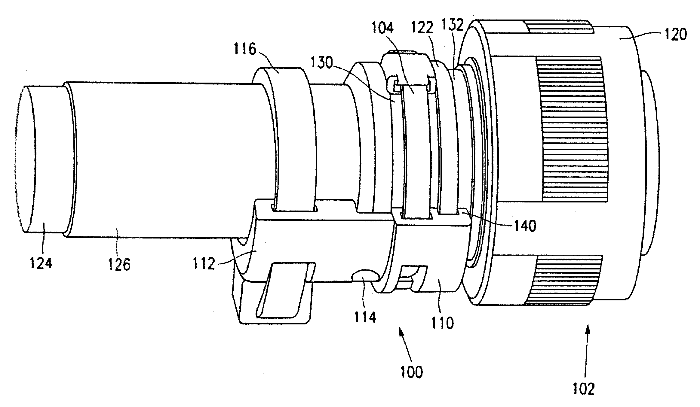
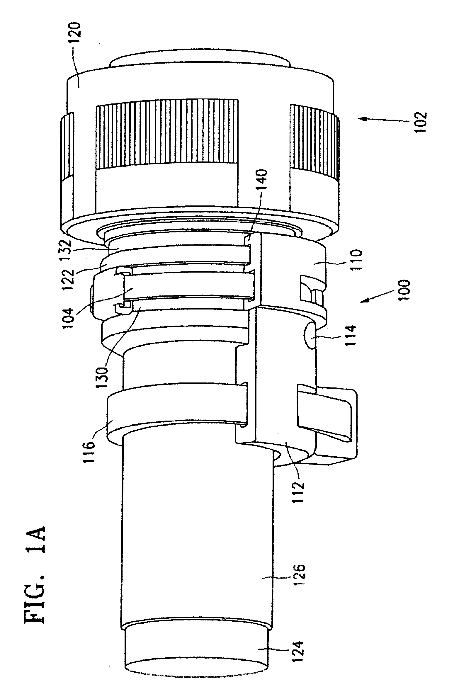
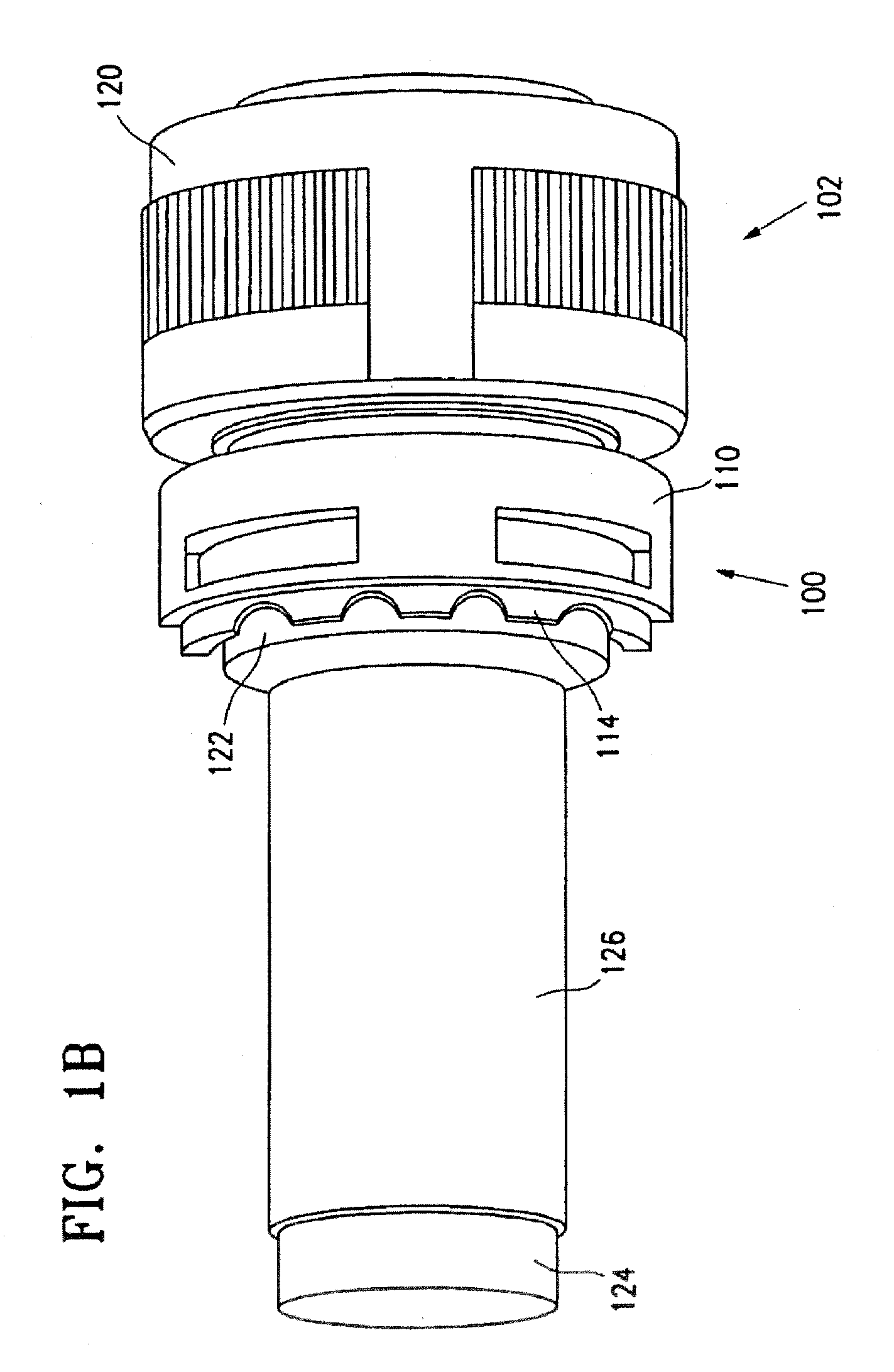
[0037]FIG. 1A is a perspective view of a backshell device 100 coupled to a connector 102 via a securing member 104. Connector 102 includes a wiring harness 124 and an overbraid or shielding sock 126 that overlies wiring harness 124.

[0038] Backshell device 100 includes a mounting section 110 and a removable extension section 112. Removable extension section 112 extends from mounting section 110 and attaches thereto via separation features 114. In one embodiment, mounting section 110 and removable extension section 112 are semi-cylindrical. In another embodiment, mounting section 110 and removable extension section 112 comprise a lightweight material including a composite material, a metallic material, a metallic composite material, or various lightweight combinations thereof.

[0039] Connector 102 includes a housing 120 having a receiving section 122 extending therefrom. In one emb...


PUM


Abstract

A backshell device and assembly are provided for achieved improved signal integrity, wherein the design of the backshell device is less complicated, more light weight, and easier to build and use than existing devices. In one embodiment, the backshell device can be coupled to adaptor which is coupled to a connector. The backshell device generally comprises a mounting section coupled to the adaptor, and an extension section extending from the mounting section. The extension section preferably comprises an increased-diameter section configured to accommodate a non-staggered or aligned arrangement of a plurality of solder sleeves of the wiring harness.

Description

CROSS-REFERENCE TO RELATED APPLICATION [0001] This application is a continuation-in-part of U.S. patent application Ser. No. 11 / 387,149, entitled “Backshell Device for a Connector,” filed Mar. 21, 2006, which claims priority to U.S. Provisional Patent Application Ser. No. 60 / 707,321, filed Aug. 10, 2005, the contents of each of which are incorporated in their entirety into this disclosure by reference.BACKGROUND OF THE INVENTION [0002] 1. Field of the Invention [0003] The present invention is directed towards connection systems for communicating electrical signals, and more particularly, to a backshell device for a connector. [0004] 2. Description of Related Art [0005] Conventional backshell devices provide a rigid and secure connection of a wiring harness to an electrical connector. Due to concerns for material strength, many conventional backshell devices are formed of aluminum or steel and are, sometimes, thick and / or heavy. In aircraft and aerospace applications, it is desirable...

Claims


Application Information

Patent Timeline
Patent Type & Authority Applications(United States)
IPC IPC(8): H01R13/627
CPCH01R13/03H01R13/622H01R13/5841H01R13/516
Inventor CARNAHAN, PAULA MARIEZAKARY, PAUL DAVID
Owner DEUT ENGINEERED CONNECTING DEVICES
Why Eureka
Try Eureka