Heat fin for small form-factor pluggable optical transceiver module

a technology of pluggable transceivers and heat fins, which is applied in the direction of electrical equipment, cooling/ventilation/heating modifications, instruments, etc., can solve the problems of premature failure of sfp, sfp modules can fail when exposed to excessive heat, and the general fragility of optical cables, so as to facilitate heat dissipation from sfp modules, improve the configuration of sfp modules

Inactive Publication Date: 2015-07-16
ENGINUITY COMM CORP
View PDF1 Cites 11 Cited by
  • Summary
  • Abstract
  • Description
  • Claims
  • Application Information

AI Technical Summary

Benefits of technology

[0007]An object of the present invention is to provide an improved SFP module configuration that facilitates heat dissipation from the SFP module.
[0009]Still another aspect of the present invention is to provide a heat fin that is configured to provide strain relief for a cable or cables connected to a SFP module.
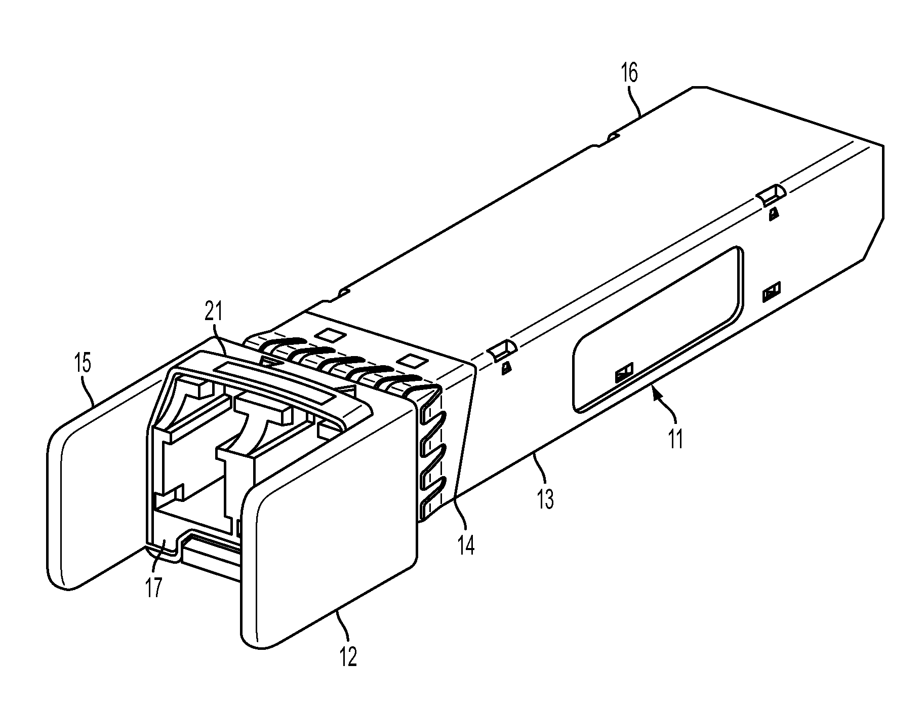
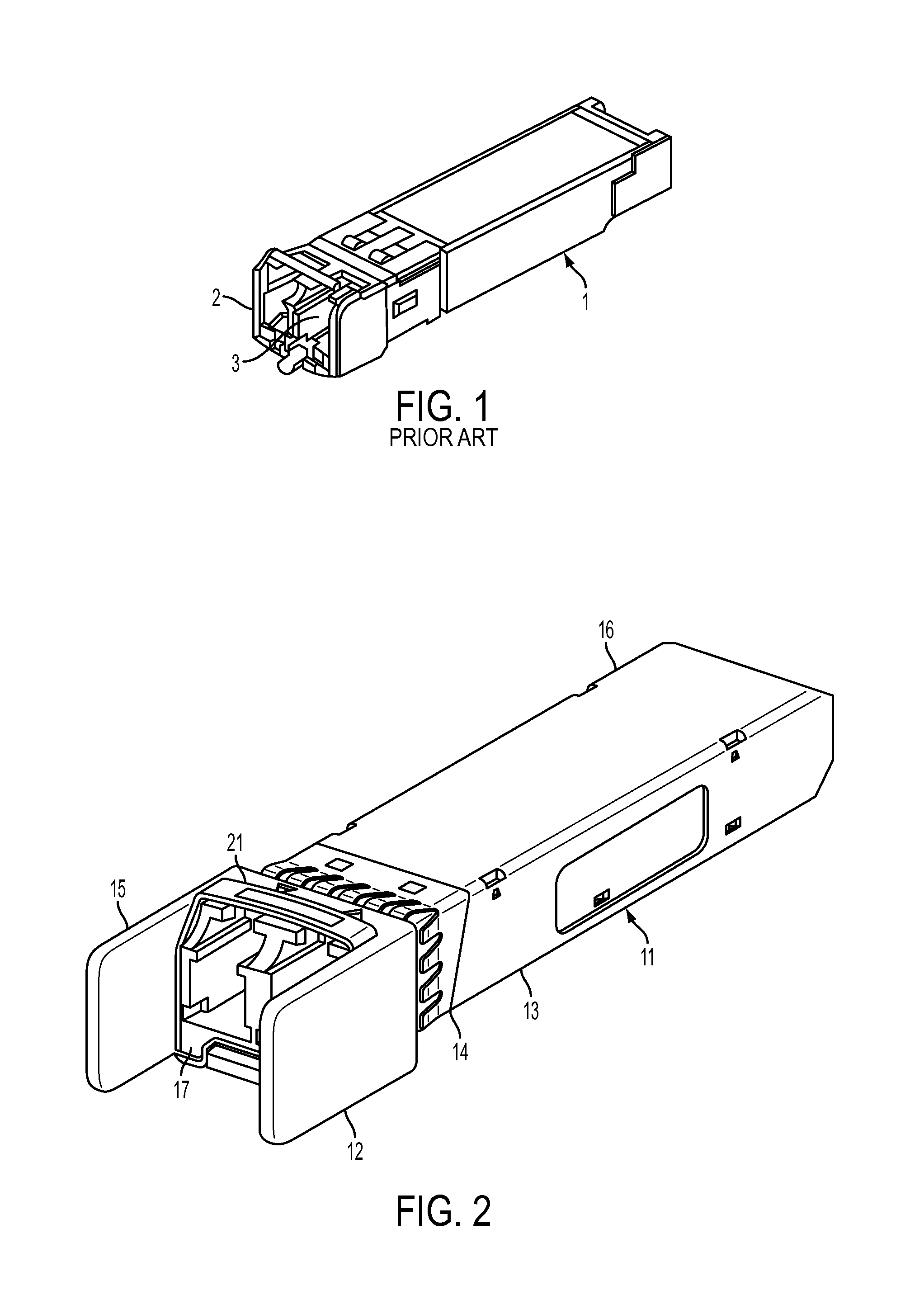
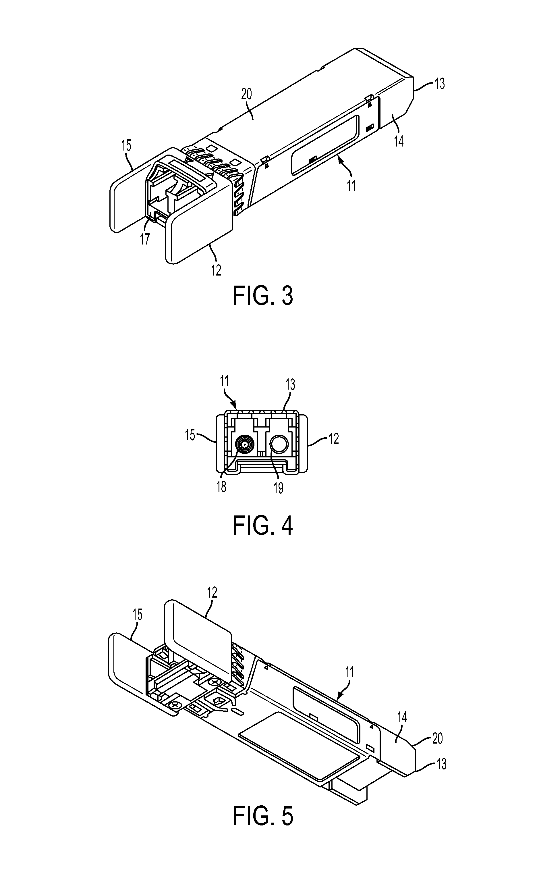
[0010]A further aspect of the present invention is to provide a small-form pluggable optical transceiver (SFP) device comprising a housing including a main body that houses SFP components, and at least one protruding member that dissipates heat generated from the SFP components and provides cable strain relief, wherein the protruding member extends beyond the main body of the housing.

Problems solved by technology

The optical cables are generally fragile and can be damaged if bent too sharply or crushed.
Additionally, SFP modules can fail when exposed to excessive heat.
However, when equipment is to be deployed in a hot environment or when additional circuitry is added within a SFP to provide, for example, additional diagnostics, thermal limits and / or heat dissipation limits may be exceeded and can potentially cause premature failure of the SFP.

Method used


Image

  • Heat fin for small form-factor pluggable optical transceiver module
  • Heat fin for small form-factor pluggable optical transceiver module
  • Heat fin for small form-factor pluggable optical transceiver module

Examples


second embodiment

[0066]FIGS. 31-41 depict a third illustrative embodiment of a SFP module 202. The third exemplary embodiment is similar to the second embodiment described above in terms of extending the housing of a SFP for heat dissipation but with modifications. For example, the SFP module 202 includes a housing 204 composed of a cover 207, a main body 206, a protruding member 214 and side members 216 and 218.

[0067]According to one embodiment, the main body 206 and the cover 207 houses SFP components (not shown) such as, for example, those deployed in conventional SFPs and optionally those deployed in SFPs having non-standard features. The SFP components include, for example, an optical interface and an electrical interface and various electronic and / or electrical components (e.g., semiconductor devices) to operate and control the SFP module 202.

[0068]SFP components and heat generation will now briefly be described. A SFP is a compact, hot-pluggable transceiver used for both telecommunication and...

fourth embodiment

[0093]In operation, the latch 121 rotates about hinge points 128 arranged opposite each other on the side surfaces 216, 218 respectively. Unlike the latch 121 illustrated in FIG. 23 which pivots approximately 90 degrees to allow the SFP module 111 to disengage from the cage, the latch 121 connected to the SFP module 202 pivots along a smaller arc so as not to exceed the height of the SFP module 202 to disengage the SFP module from the cage. The hinged ends of the latch arms 129 and 130 can be configured to bias the SFP module away from the cage and the latch 121 in which the SFP module is mounted as the latch 121 is pivoted. The length of the latch 121 in the fourth embodiment extends beyond the length of the protruding member 214 to allow for the latch 121 to rotate and operate in the manner described above.

[0094]FIG. 41 illustrates an exemplary cover 207 that protects the main body 206. The cover 207 is a separate piece that attaches to the main body 206. The cover 207 substantial...


PUM


Abstract

A small-form pluggable optical transceiver (SFP) device comprising a housing including a main body that houses SFP components, and at least one protruding member that dissipates heat generated from the SFP components, wherein the protruding member extends beyond the main body of the housing.

Description

[0001]This application claims the benefit of U.S. provisional application Ser. No. 61 / 927,394, filed Jan. 14, 2014, the entire contents of which are incorporated herein by reference.FIELD OF THE INVENTION[0002]The present invention relates generally to a heat fin for an electrical component. More particularly, the present invention relates to a heat fin for a cable receiving electrical component that permits the component to dissipate more heat than a similar component without the heat fins and to provide strain relief to the received cable. Still more particularly, the present invention relates to a heat fin for a small form-factor pluggable (SFP) transceiver module.BACKGROUND OF THE INVENTION[0003]Public communication carriers (hereinafter, “telcos”) are using more and more optical cable facilities to deliver services to customers because of the ability of optical cables to support high bandwidth. At a customer site, a means is often required to convert the optical signals to elec...

Claims


Application Information

Patent Timeline
Patent Type & Authority Applications(United States)
IPC IPC(8): H05K7/20
CPCH05K7/20409G02B6/4269G02B6/4246
Inventor LEBO, STEPHEN KENTCORP, DAVID OWEN
Owner ENGINUITY COMM CORP
Why Eureka
Try Eureka