Fabric and yarn structures for improving signal integrity in fabric-based electrical circuits

a technology of fabric-based electrical circuits and conductive yarns, applied in the direction of yarn, weaving, conductive pattern formation, etc., can solve the problems of unsuitability for incorporation in a fabric, and achieve the effects of improving signal integrity in fabric-based electrical circuits, reducing crosstalk in fabric-based circuits, and improving conductive yarn structures

Inactive Publication Date: 2008-11-20
NORTH CAROLINA STATE UNIV
View PDF77 Cites 31 Cited by
  • Summary
  • Abstract
  • Description
  • Claims
  • Application Information

AI Technical Summary

Benefits of technology

[0013]Another woven electrical network of the present invention includes first and second twisted pair conductive yarn structures. Each of the first and second twisted pair conductive yarn structures is woven to a fabric in a first direction. One conductor in each of the twisted pair conductive yarn structures is connected to ground. The other conductor in at least one of the twisted pair conductive yarn structures is connected to an AC signal source. When the AC signal is applied to the conductor, the grounded second conductors of the twisted pair conductive yarn structures block electromagnetic fields emanating from the first conductive yarn of the first twisted pair conductor and thereby reduce crosstalk between the first and second twisted pair conductive yarn structures.
[0014]According to another aspect, the present invention includes methods and systems for creating conductive thread structures with improved crosstalk resistance while the thread structures are being woven or knitted into a fabric. For example, a coaxial structure may be created by leno weaving conductive threads into a fabric. A similar process may be used to create a twisted pair structure while leno weaving the yarns that make up the twisted pair structure into a fabric. One advantage of creating the structures while the structures are being woven or knitted into a fabric is that the time required to produce such structures is reduced over methods where coaxial or twisted pair structures are formed in advance of making the fabric. Another advantage of forming the structures during the knitting or weaving process is that the weaving can be altered during the formation of the structures to create floats for selective electrical connection and disconnection.
[0016]Accordingly, it is an object of the invention to provide improved methods and systems for reducing crosstalk in fabric-based circuits.
[0017]It is another object of the invention to provide improved conductive yarn structures for improving signal integrity in fabric-based electrical circuits.

Problems solved by technology

Conventional wires lack one or more of these characteristics, making them unsuitable for incorporation in a fabric.

Method used


Image

  • Fabric and yarn structures for improving signal integrity in fabric-based electrical circuits
  • Fabric and yarn structures for improving signal integrity in fabric-based electrical circuits
  • Fabric and yarn structures for improving signal integrity in fabric-based electrical circuits

Examples


Embodiment Construction

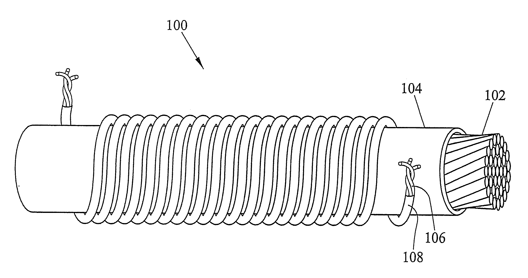
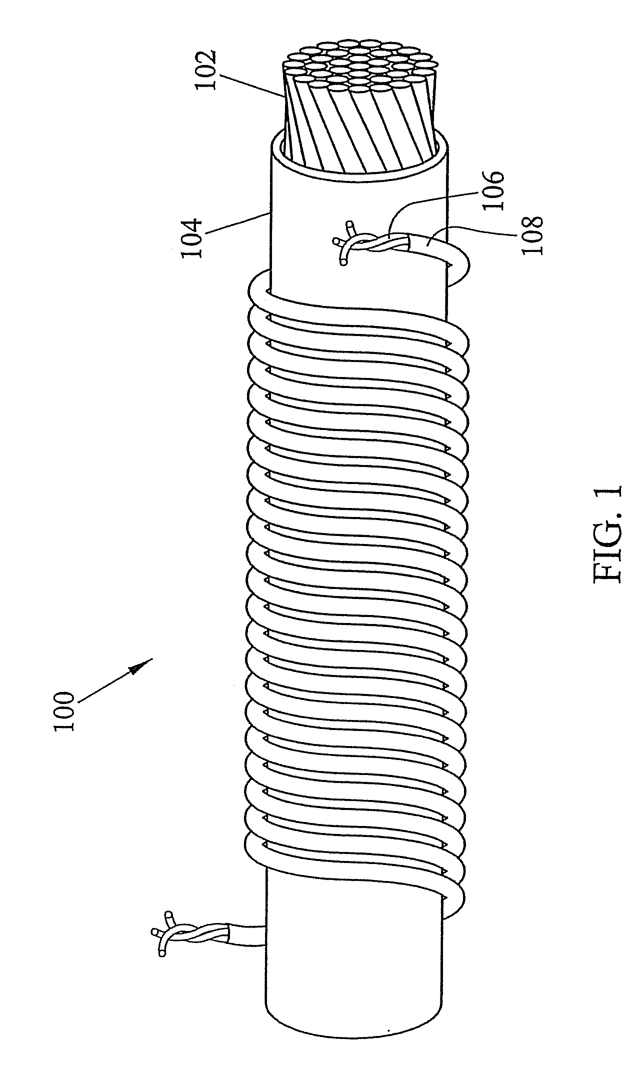
[0055]The present invention includes conductive yarn structures for improving signal integrity in fabric-based electrical networks. FIG. 1 illustrates an example of one conductive yarn structure suitable for improving signal integrity in fabric-based electrical networks according to an embodiment of the present invention. Referring to FIG. 1, a conductive yarn structure 100 comprises a coaxial conductive yarn structure. Coaxial conductive yarn structure 100 includes an inner conductive yarn 102 surrounded by an insulating layer 104 and an outer conductive yarn 106, which is preferably also surrounded by an insulating layer 108. Inner conductive yarn 102 includes a plurality of conductive strands being twisted together. The conductive strands may be made of any suitable conductive material, such as such as copper, gold, steel, aluminum, silver, or iron or conductive polymers (inherently conductive polymeric materials, such as polypyrrole, polyacetylene, polythiophene and polyaniline,...


PUM

PropertyMeasurementUnit
distancesaaaaaaaaaa
diameteraaaaaaaaaa
conductiveaaaaaaaaaa

Abstract

Coaxial and twisted pair conductive yarn structures reduce signal crosstalk between adjacent lines in woven electrical networks. A coaxial conductive yarn structure includes an inner conductive yarn having a plurality of conductive strands twisted together. An outer conductive yarn is wrapped around the inner conductive yarn. An insulating layer separates the inner and outer yarns. A twisted pair conductive yarn structure includes first and second conductive yarns, each including a plurality of conductive strands being twisted together. The first and second conductive yarns are twisted together to form a helical structure. In a woven electrical network, at least one conductor of adjacent conductive yarn structures is connected to ground to reduce signal crosstalk. Coaxial and twisted pair yarn structures may also be formed simultaneously with weaving or knitting the threads that make up the structures into a fabric.

Description

RELATED APPLICATIONS[0001]This application is a divisional of U.S. patent application Ser. No. 10 / 609,074, filed Jun. 27, 2003, which claims the benefit of U.S. Provisional Patent Application Ser. No. 60 / 392,591, filed Jun. 28, 2002 and U.S. Provisional Patent Application Ser. No. 60 / 447,438, filed Feb. 14, 2003, the disclosures of each of which are incorporated herein by reference in their entireties.GOVERNMENT INTEREST[0002]This invention was made with U.S. Government support under Grant No. N39998-98-C3566 awarded by the Department of Defense-Defense Advanced Research Projects Agency. The U.S. Government has certain rights in the invention.TECHNICAL FIELD[0003]The present invention relates to methods and systems for improving signal integrity in fabric-based electrical circuits. More particularly, the present invention relates to new fabric and yarn structures and methods for making the same for solving signal integrity related problems, such as crosstalk, in woven or knitted ele...

Claims


Application Information

Patent Timeline
Patent Type & Authority Applications(United States)
IPC IPC(8): D03D15/00D02G3/44D02G3/12D02G3/00D03C3/00D03C7/00D02G3/38H05K3/10
CPCD02G3/38D02G3/441H05K3/10H05K2201/029H05K2201/09809Y10T442/105Y10T442/109Y10T442/3065Y10T442/3382Y10T442/339Y10T442/3976Y10T442/655
Inventor DHAWAN, ANUJGHOSH, TUSHAR K.SEYAM, ABDELFATTAH M.MUTH, JOHN
Owner NORTH CAROLINA STATE UNIV
Why Eureka
Try Eureka