
System and method for longitudinal and lateral jetting in a wellbore

a wellbore and longitudinal technology, applied in the direction of directional drilling, drilling accessories, borehole/well accessories, etc., can solve the problems of inability to exploit thin production horizons, high cost, and inability to enhance production in some applications, so as to achieve the effect of increasing hydraulic pressur

Inactive Publication Date: 2010-09-30
AXS TECH
View PDF50 Cites 31 Cited by
  • Summary
  • Abstract
  • Description
  • Claims
  • Application Information

AI Technical Summary

Benefits of technology

[0021]In another aspect of the invention, a method for radial jetting a well bore in a system having an under-reamer and lateral jetting system as above is provided, the method comprising the steps of: a) applying a hydraulic pressure to an upper surface of the under-reamer tool to effect under-reaming and access to a formation; b) introducing a drop ball to the drill string and pumping the drop ball to effect seating of the drop ball within the ball seat; c) increasing hydraulic pressure within the drill string to shear the shear pin and cause the sliding sleeve to move from the closed position to the open position; d) advancing a jet hose in the drill string such that the jet hose seats within the jetting trough and is radially deflected along the jetting trough to the jetting orifice; and e) conducting lateral jetting with the jet hose.

Problems solved by technology

However, each of these technologies can be extremely costly such that the cost presents a significant barrier to enhanced production in some applications.
Moreover, such techniques may not be able to exploit thin production horizons.
Generally, the limitations of these production enhancement technologies results in what the industry refers to as by-passed production.
While the prior art may provide a partial solution, each are limited in various ways as briefly discussed below.
In particular, past systems may be limited by the practical effectiveness of the system downhole or by inherent problems in the design of the systems.
Such problems may include the strength, durability and accuracy of a flexible shaft and / or the effectiveness of a ball cutter.
Other problems include the number of steps required, the complexity of the systems and, hence the maintenance costs associated with such systems.
Abrasive jet techniques and rotary techniques may be further limited in narrow casing ID's deployments and problems of ports that introduce potential tear / binding points.

Method used


Image

  • System and method for longitudinal and lateral jetting in a wellbore
  • System and method for longitudinal and lateral jetting in a wellbore
  • System and method for longitudinal and lateral jetting in a wellbore

Examples


Embodiment Construction

[0029]With reference to the figures a downhole tool system enabling lateral jetting from within well casing is described.

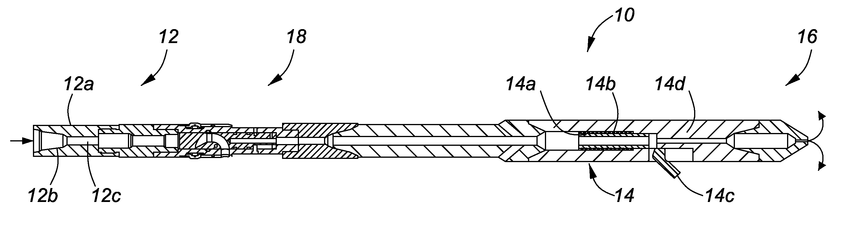
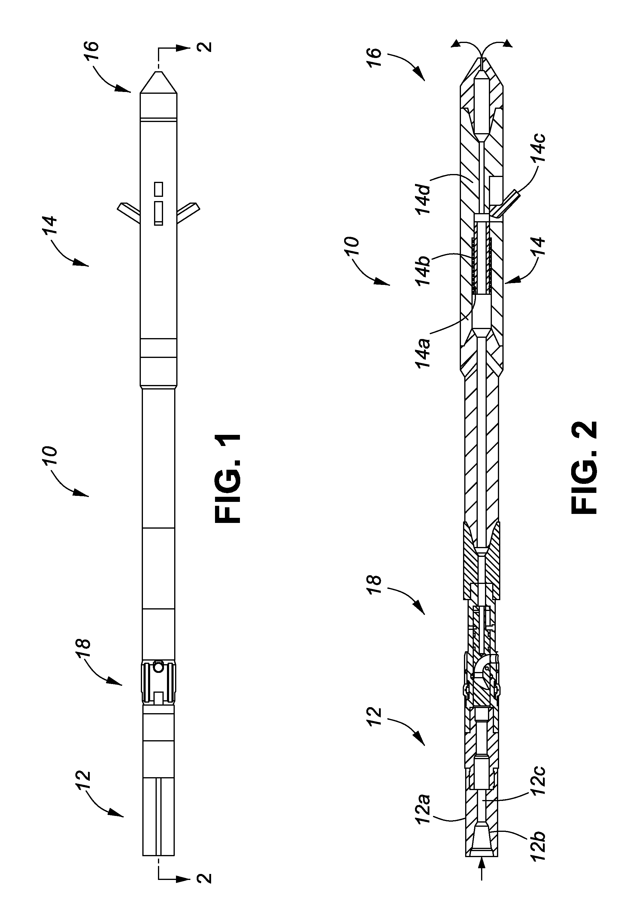
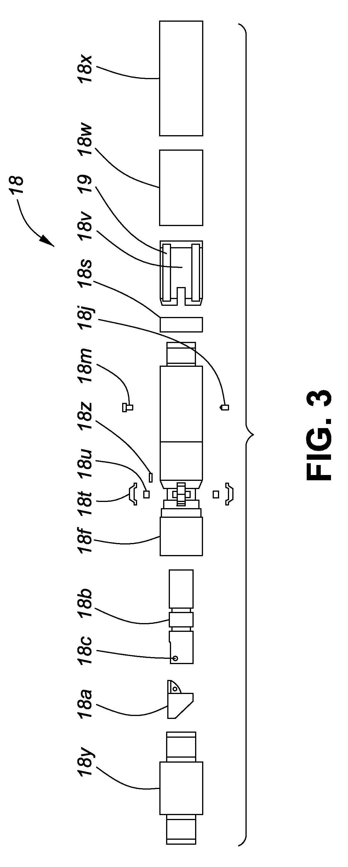
[0030]As shown in FIGS. 1 and 2, a lateral jetting system 10 includes a lateral jetting section (LJS) 18, an under-reamer section 14, a bullnose 16 and a crossover sub 12.

Overview

[0031]In an operation to under-ream and laterally jet a cased well, the system 10 is attached to a drill / coiled tubing string (not shown) using the crossover over sub 12. The LJS 18 is attached to the cross-over sub and the LJS is attached to the under-reamer 14 which in turn is attached to the bullnose 16.

[0032]The system 10 is pushed into the well to a desired depth and drilling fluid is circulated down through the coiled tubing, through the cross-over sub, LJS, under-reamer and out through the bullnose as shown in FIG. 2.

[0033]At the commencement of the under-reaming operation, the operator increases the flow rate of drilling fluid through the system such that hydraulic pressure acting...


PUM


Abstract

A system and method for enabling longitudinal and radial drilling in a wellbore is described. The system and method enable an operator to perforate the casing of a wellbore with an under-reamer at the end of a drill string and, without removing the drill string from the wellbore, initiate and complete lateral jetting of the wellbore into the surrounding formation. The system utilizes a perforation tool having a ball seat, which upon seating a drop ball in the ball seat enables the perforation tool to move from a closed position to an open position thereby allowing access to the formation using a jetting tool. Prior to seating the drop ball, an under-reaming operation may be performed using a hydraulic pressure activated under-reaming tool.

Description

RELATED APPLICATIONS[0001]This application claims the benefit of priority under 35 U.S.C. §119(e) from U.S. Provisional Patent Application 61 / 163,697, entitled “System and Method For Longitudinal and Lateral Jetting in a Wellbore”, which was filed Mar. 26, 2009, the disclosure of which is incorporated herein by reference.FIELD OF THE INVENTION[0002]A system and method for enabling longitudinal and radial drilling in a wellbore is described. The system and method enable an operator to perforate the casing of a wellbore with an under-reamer at the end of a drill string and, without removing the drill string from the wellbore, initiate and complete radial drilling of the wellbore into the surrounding formation. The system utilizes a perforation tool having a ball seat, which upon seating a drop ball in the ball seat enables the perforation tool to move from a closed position to an open position thereby allowing access to the formation using a jetting tool. Prior to seating the drop bal...

Claims


Application Information

Patent Timeline
Patent Type & Authority Applications(United States)
IPC IPC(8): E21B34/06E21B33/12
CPCE21B7/18E21B29/06E21B10/322
Inventor SOBY, MICHAELJOSEPH, DALE
Owner AXS TECH
Learn More