Integrative structure for aircraft fairing

Inactive Publication Date: 2010-09-30
AIRBUS OPERATIONS SL
View PDF7 Cites 18 Cited by
  • Summary
  • Abstract
  • Description
  • Claims
  • Application Information

AI Technical Summary

Benefits of technology

[0008]Thus, the present invention refers to a joining structure for aircraft fairing, in particular a joining structure for aircraft fairing to be arranged between the horizontal stabilizer and the vertical stabilizer or fuselage section, such that said structure allows assembly of the fairing, reducing the number of mechanical parts for adjustment thereof and reducing considerably the weight of said integrative structure. Thus, in the fairing joining structure according to the invention, said fairing is joined rigidly to the horizontal stabilizer, resting in turn on the vertical stabilizer or fuselage section, its main function being that of minimizing the aerodynamic impact of the joint between both said surfaces.
[0010]The novel integrative fairing structure according to the invention solves the problem of adjusting the fairing without having to use serrated plates and without having to serrate the angular fittings, while maintaining the structural efficiency of the whole unit and simplifying the design, manufacture and assembly of the above components, resulting ultimately in cost-savings.

Problems solved by technology

The conventional used joining system poses various problems.
On the one hand, the additional weight of the different mechanical parts for joining and adjusting the fairing is considerable; on the other hand, such specific parts (with special serrations, for example) have a high cost; moreover the assembly and maintenance of the above fairing fixing system is very complex.
Furthermore, the conventional used systems do not allow the adjustment of the top or bottom part of each associated fairing, which prevents advantageous correction of the tolerances arising during manufacture thereof (the fairing comprises top and bottom parts, respectively, in its joints with the top and bottom part of the fuselage, respectively).

Method used


Image

  • Integrative structure for aircraft fairing
  • Integrative structure for aircraft fairing
  • Integrative structure for aircraft fairing

Examples


Embodiment Construction

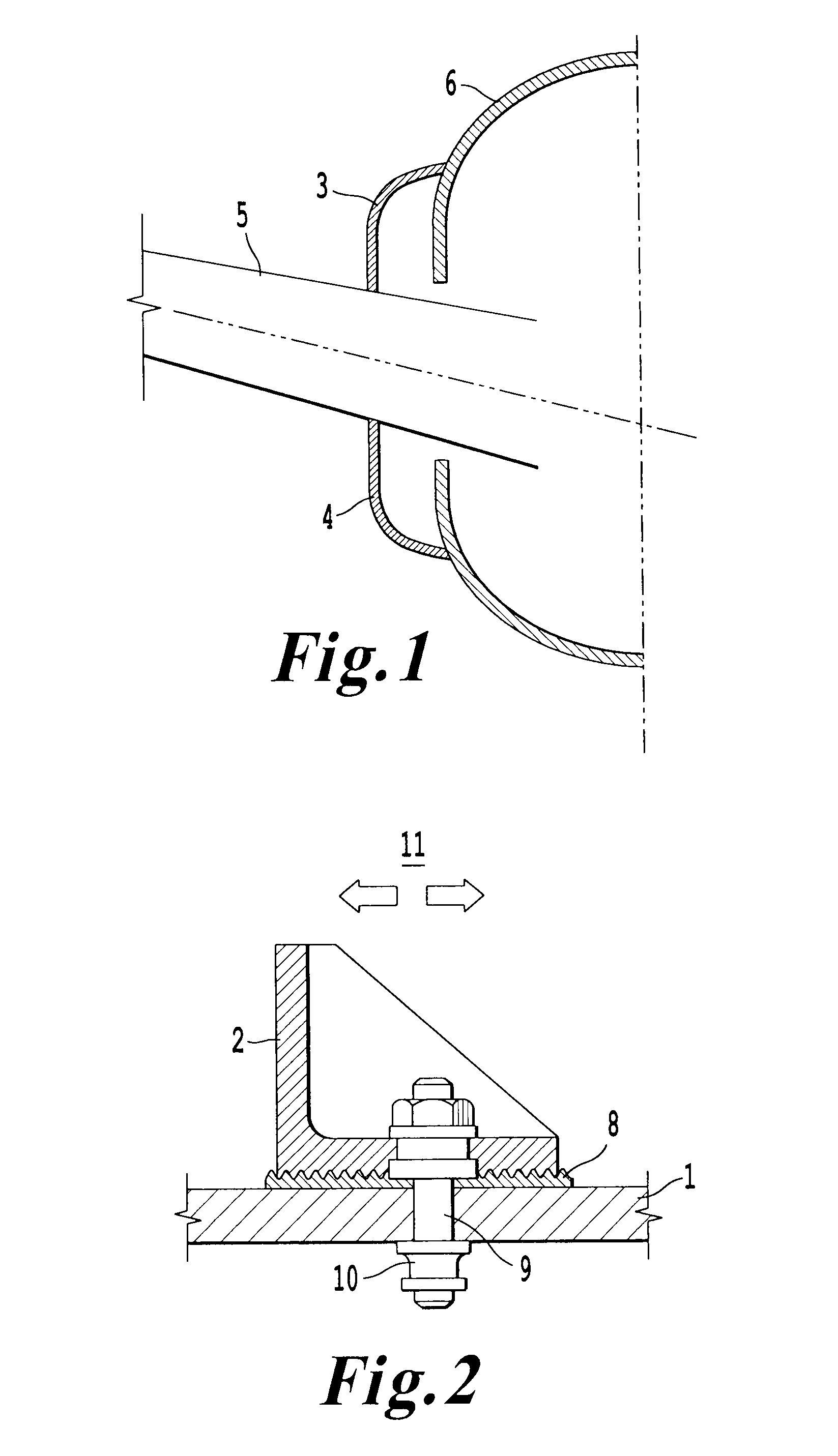
[0016]According to that shown in FIG. 1, the top and bottom fairing, 3 and 4, are joined on one side to the skin of the horizontal aerofoil 5 in question and, on the other side, to the fuselage or vertical aerofoil 6 of the aircraft.

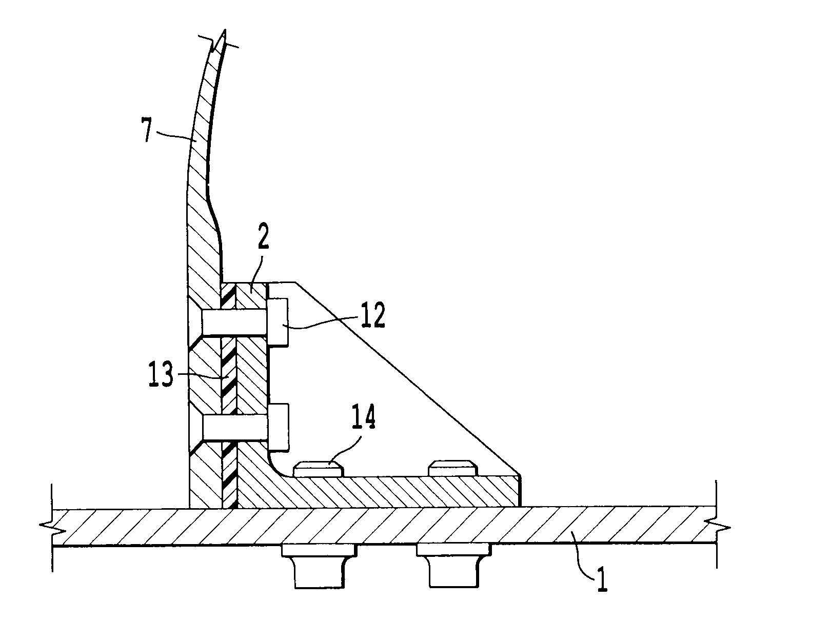
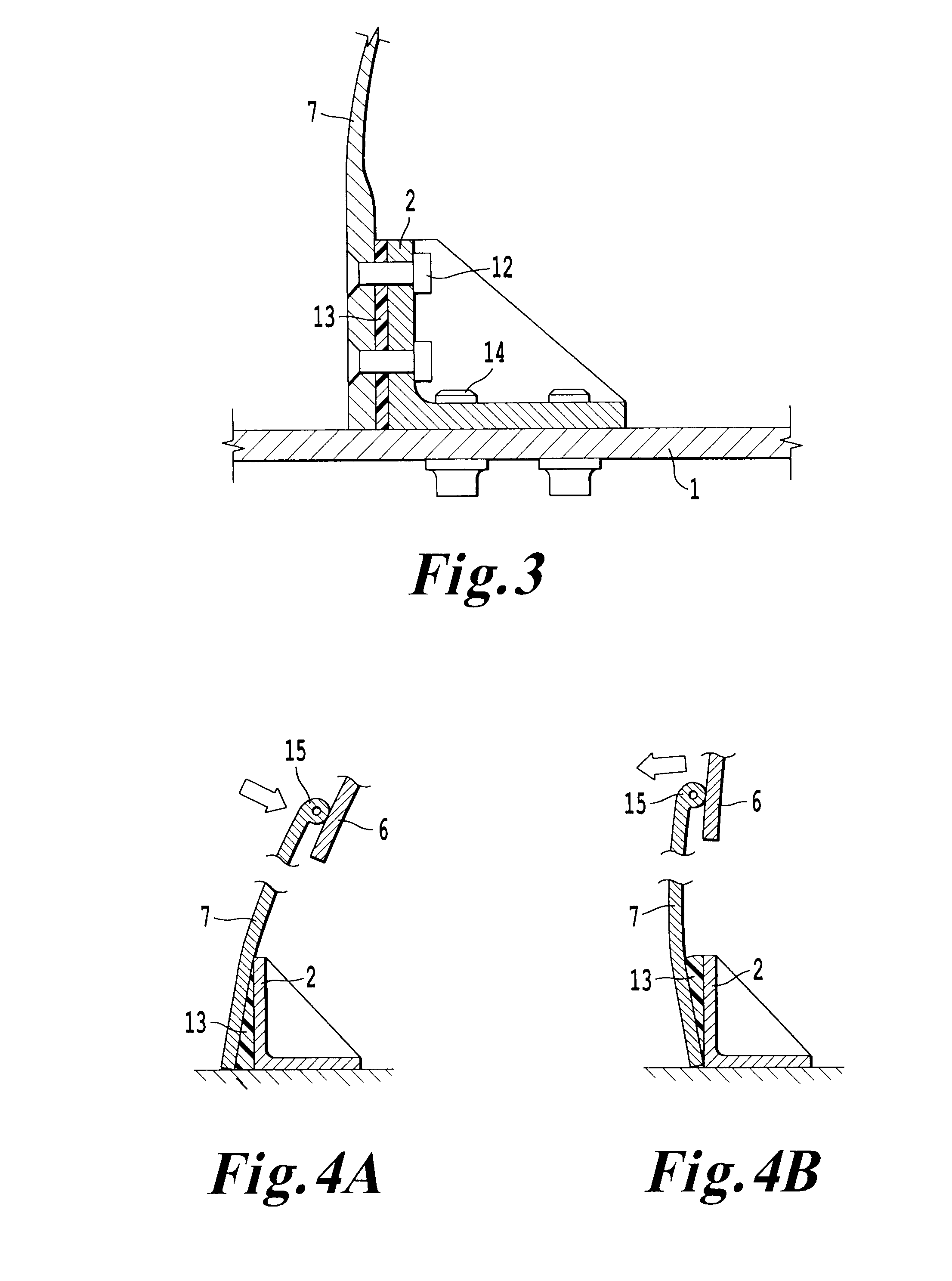
[0017]According to the known art, as described in FIG. 2, joining of the fairing 7 (whether it be the top fairing 3 or bottom fairing 4) to the skin 1 of the horizontal stabilizer of an aircraft is performed by means of a system of separate metal fittings 2 which are joined to said skin 1 of the horizontal stabilizer. Specifically, said joint comprises a serrated plate 8 (usually in the transverse direction of the aircraft) fixed to the skin 1 of the horizontal stabilizer by means of stud pins 9 and by means of fittings 2 in the shape of angle which are serrated in the same direction as the plate 8 and which reproduce the geometrical surface of the fairing 7. The fairing 7 is fixed to the fitting 2 by means of screwed joining members (not shown) which ar...


PUM


Abstract

Joining structure for aircraft fairing (7), said fairing (7) being arranged between the horizontal stabilizer and the vertical stabilizer or fuselage section (6) of said aircraft, said structure comprising fittings (2) in the shape of angle, said fittings in turn comprising a vertical surface and a horizontal surface, the fittings (2) being joined via their vertical surface to the fairing (7) by means of removable fixing parts (12), said structure also comprising a deformable resilient element (13) between the fairing (7) and the vertical surface of the fitting (2), such that said resilient element (13) is able to compensate for the necessary deformation play and the manufacturing and assembly tolerances of the fittings (2), the fairing (7), the horizontal stabilizer and the vertical stabilizer or fuselage section (6) by means of different torques for tightening of the above parts.

Description

FIELD OF THE INVENTION[0001]The present invention relates to a joining structure for aircraft fairing, in particular a joining structure for aircraft fairing to be arranged between the horizontal stabilizer and the vertical stabilizer or fuselage section.PRIOR ART[0002]The main structural components of an aircraft are: the central fuselage, the engines, which provide the aircraft with the necessary thrust, the wing, which generates lift, and the horizontal stabilizer and the vertical stabilizer, which are used to control the aircraft. In order to minimize the aerodynamic impact of the external surfaces of the above main structural components, auxiliary surfaces are used to cover the parts for joining said main structures to the aircraft; at the same time these external surfaces ensure smoother cross-sectional profiles, thus reducing the aerodynamic resistance of said surfaces in the different flying positions. It must be taken into account, moreover, that, in the particular case of ...

Claims


Application Information

Patent Timeline
IPC IPC(8): B64C1/06
CPCB64C1/26B64C5/02F16B5/025B64C7/00
Inventor LOBO BARROS, ABELLOZANO GARCIA, JOSE LUIS
Owner AIRBUS OPERATIONS SL
Why Eureka
Try Eureka