Shearing Cutter on a Degradation Drum

a technology of degradation drum and shearing cutter, which is applied in the field of cutting tools, can solve the problems of tools wearing and the surface of the pavement to degrad

Inactive Publication Date: 2010-09-30
NOVATEK IP
View PDF12 Cites 84 Cited by
  • Summary
  • Abstract
  • Description
  • Claims
  • Application Information

AI Technical Summary

Benefits of technology

[0007]In another aspect of the present invention, a degradation drum comprises a pick secured to an outer surface of the drum through a block rigidly mounted to the outer surface. The block comprises a bore with an inner surface, the shank being secured within the bore. At least one pick comprises a shearing cutter comprising a flat surface. The shearing cutter and the shank are co-axially arranged about a central axis. The flat su

Problems solved by technology

In asphalt or concrete milling, an array of cutting tools supported by a drum may enga

Method used


Image

  • Shearing Cutter on a Degradation Drum
  • Shearing Cutter on a Degradation Drum
  • Shearing Cutter on a Degradation Drum

Examples


Embodiment Construction

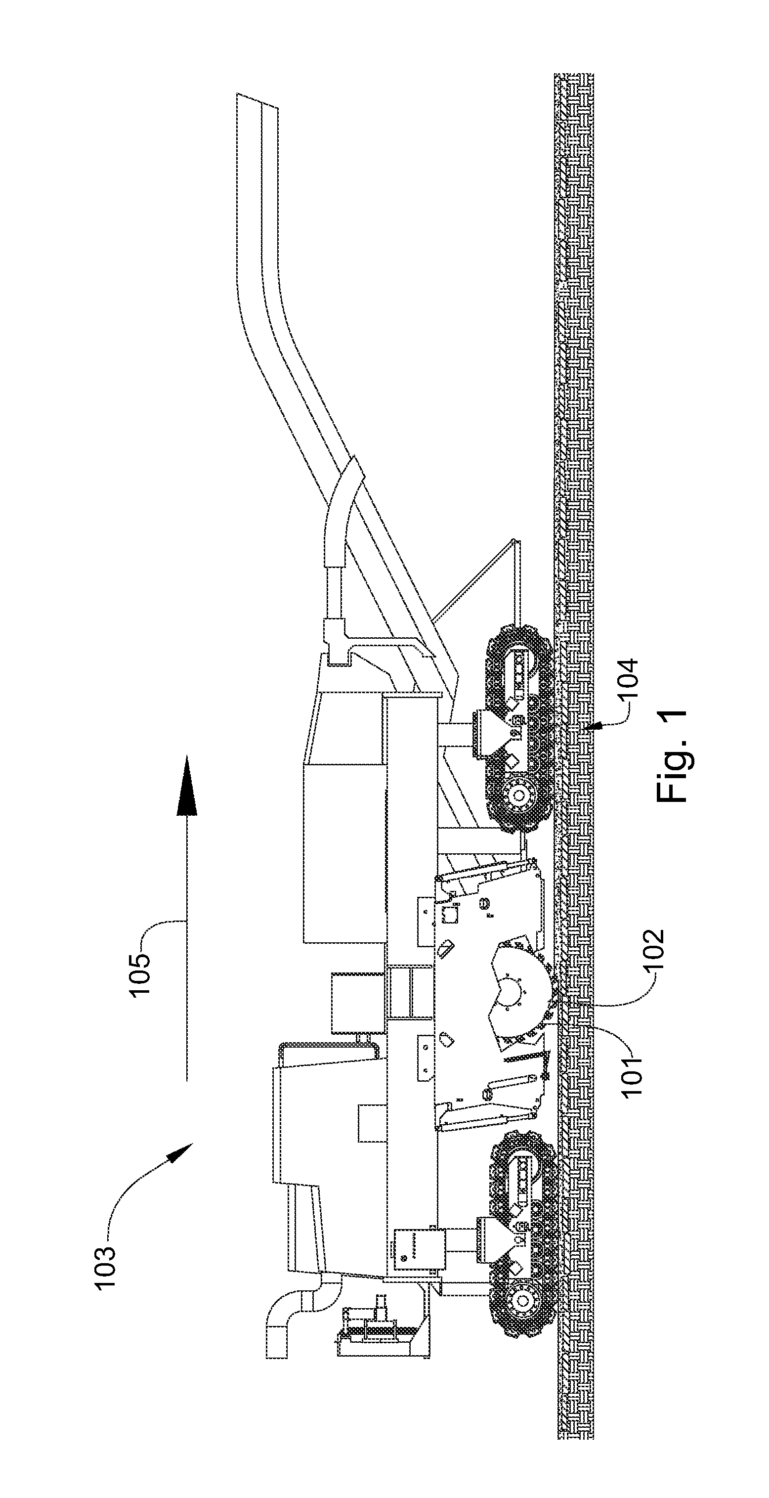
[0026]FIG. 1 is a cross-sectional diagram that shows a plurality of picks 101 attached to a driving mechanism, such as a rotatable drum 102 attached to the underside of a pavement milling machine 103. The milling machine 103 may be an asphalt planer used to degrade man-made formations 104 such as pavement prior to placement of a new layer of pavement. The picks 101 may be attached to the drum 102, bringing the picks 101 into engagement with the formation 104. A holder, such as a block welded or bolted to the drum 102, is attached to the driving mechanism and a shank of the pick 101 is inserted into the holder. The holder may hold the picks 101 at an angle offset from the direction of rotation, such that the picks 101 engage the formation 104 at a preferential angle. Arrow 105 discloses the milling machine's direction of travel.

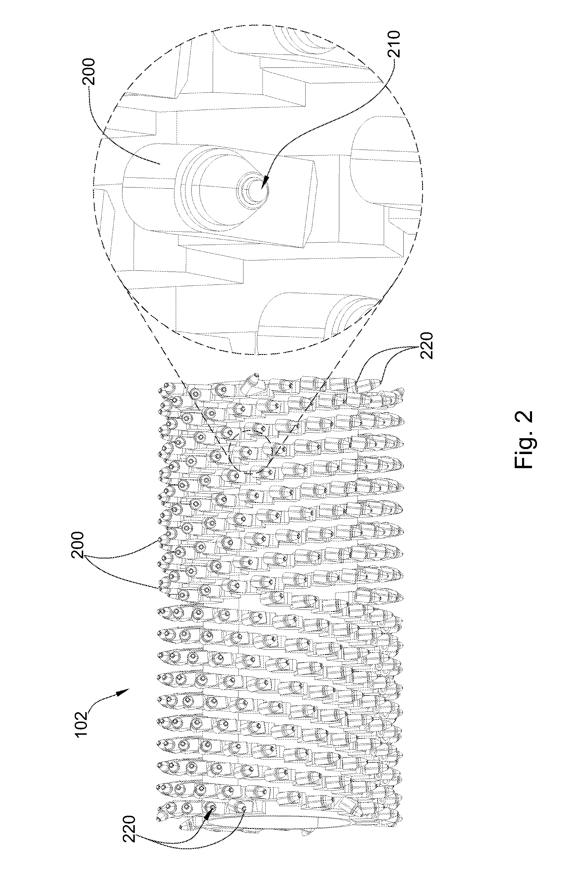
[0027]Referring to FIG. 2, a rotary degradation drum 102 for harder pavements, such as concrete is disclosed. The degradation drum 102 may comprise a pluralit...


PUM


Abstract

In one aspect of the present invention, a pick comprises a forward end and rearward end. The forward end comprises a shearing cutter and the rearward end comprises a shank. The shank and the shearing cutter are arranged co-axially about a central axis. The shearing cutter is supported by an enlarged section that narrows towards the shearing cutter and that has a greater cross section than the shank along a plane substantially perpendicular to the central axis. The shearing cutter comprises a flat surface that is substantially perpendicular to the central axis.

Description

CROSS REFERENCE TO RELATED APPLICATIONS[0001]This application is a continuation-in-part of U.S. application Ser. No. 11 / 424,806 filed on Jun. 16, 2006. This application claims priority to U.S. application Ser. No. 11 / 424,806, which is herein incorporated by reference for all that it teaches.BACKGROUND OF THE INVENTION[0002]The present invention relates to a cutting tool that may be used in asphalt, mining, excavation, and other industries. In asphalt or concrete milling, an array of cutting tools supported by a drum may engage the paved surface causing both the paved surface to degrade, and the tools to wear. Typically, conical cutting elements are used in milling. These conical cutting elements are rotationally supported by a block or drum on a milling drum. The blocks are generally adapted to hold the picks at an offset angle such that the picks will rotate as they engage the formation. Rigidly fixed shearing cutters have also been used in the milling drum prior art.[0003]U.S. Pat...

Claims


Application Information

Patent Timeline
IPC IPC(8): E21C35/18E21C35/197E21C25/10E21C35/183
CPCE21C2035/1806E21C35/183E21C35/1831
Inventor HALL, DAVID R.JEPSON, JEFFCROCKETT, RONALD B.
Owner NOVATEK IP
Why Eureka
Try Eureka