Fluid storage container
a technology of fluid storage container and storage container, which is applied in the direction of printing, etc., can solve the problems of inability to ensure sufficient strength, cracks or other damage to the case body, and ink stored inside may leak out, so as to prevent the leakage of fluid from the first and/or second fluid storage unit, suppress the inside wall damage, and improve the effect of strength
- Summary
- Abstract
- Description
- Claims
- Application Information
AI Technical Summary
Benefits of technology
Problems solved by technology
Method used
Image
Examples
first embodiment
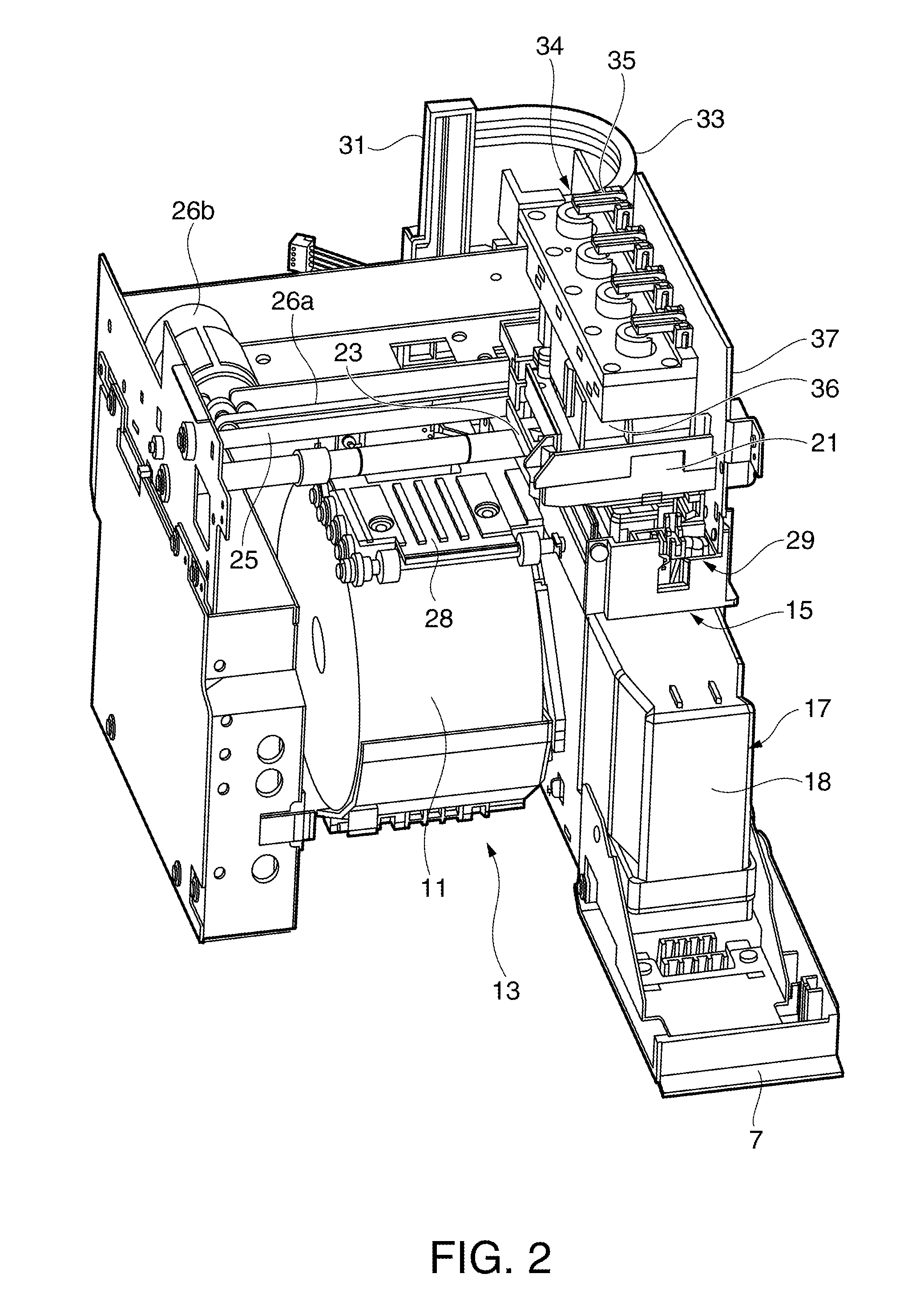
[0104]With the ink cartridge 17 described as a fluid storage container according to the invention, waste ink can be stored in a waste ink storage unit 41a and ink packs 47 filled with ink can be stored in an ink pack storage unit 41b because a waste ink storage unit 41a and an ink pack storage unit 41b are formed as fluid storage units on opposite sides of a divider 48.
[0105]In addition, with the ink cartridge 17 according to this embodiment of the invention the case body 41 in which the recessed waste ink storage unit 41a and ink pack storage unit 41b are formed on opposite sides of the divider 48 has an I-beam shape in cross section with a perimeter wall 49 surrounding the divider 48. As a result, the width of the parts of the perimeter wall 49 forming the waste ink storage unit 41a and ink pack storage unit 41b respectively can be reduced and the strength of the case body 41 can be greatly increased. Damage to the case body 41 when the ink cartridge 17 is dropped or subject to im...
second embodiment
[0109]FIGS. 12A and 12B illustrate a case body of an ink cartridge according to the invention, FIG. 12B being a plan view from the waste ink storage unit side. FIG. 13 is a section view through line C-C shown in FIG. 12A. FIG. 14 is an oblique view of the case body shown in FIGS. 12A and 12B from the ink pack storage unit side.
[0110]Note that identical parts and parts having the same function as the first embodiment described above are identified by the same reference numerals in these figures, and further description thereof is omitted or simplified.
[0111]As shown in FIG. 12B, an inside wall 64 on the divider 48A side as in the first embodiment, and an outside wall 65 disposed opposite the inside wall 64 with a gap there between, are disposed to three sides of the perimeter wall 49 of the case body 41A. The inside wall 64 and outside wall 65 are connected by ribs 66 disposed around the circumference with a gap there between. The ribs 66 are disposed at positions not including the c...
PUM
 Abstract
Description
Claims
Application Information
 - R&D
- Intellectual Property
- Life Sciences
- Materials
- Tech Scout
- Unparalleled Data Quality
- Higher Quality Content
- 60% Fewer Hallucinations
Browse by: Latest US Patents, China's latest patents, Technical Efficacy Thesaurus, Application Domain, Technology Topic, Popular Technical Reports.
© 2025 PatSnap. All rights reserved.Legal|Privacy policy|Modern Slavery Act Transparency Statement|Sitemap|About US| Contact US: help@patsnap.com


