Imaging apparatus having a zoom function

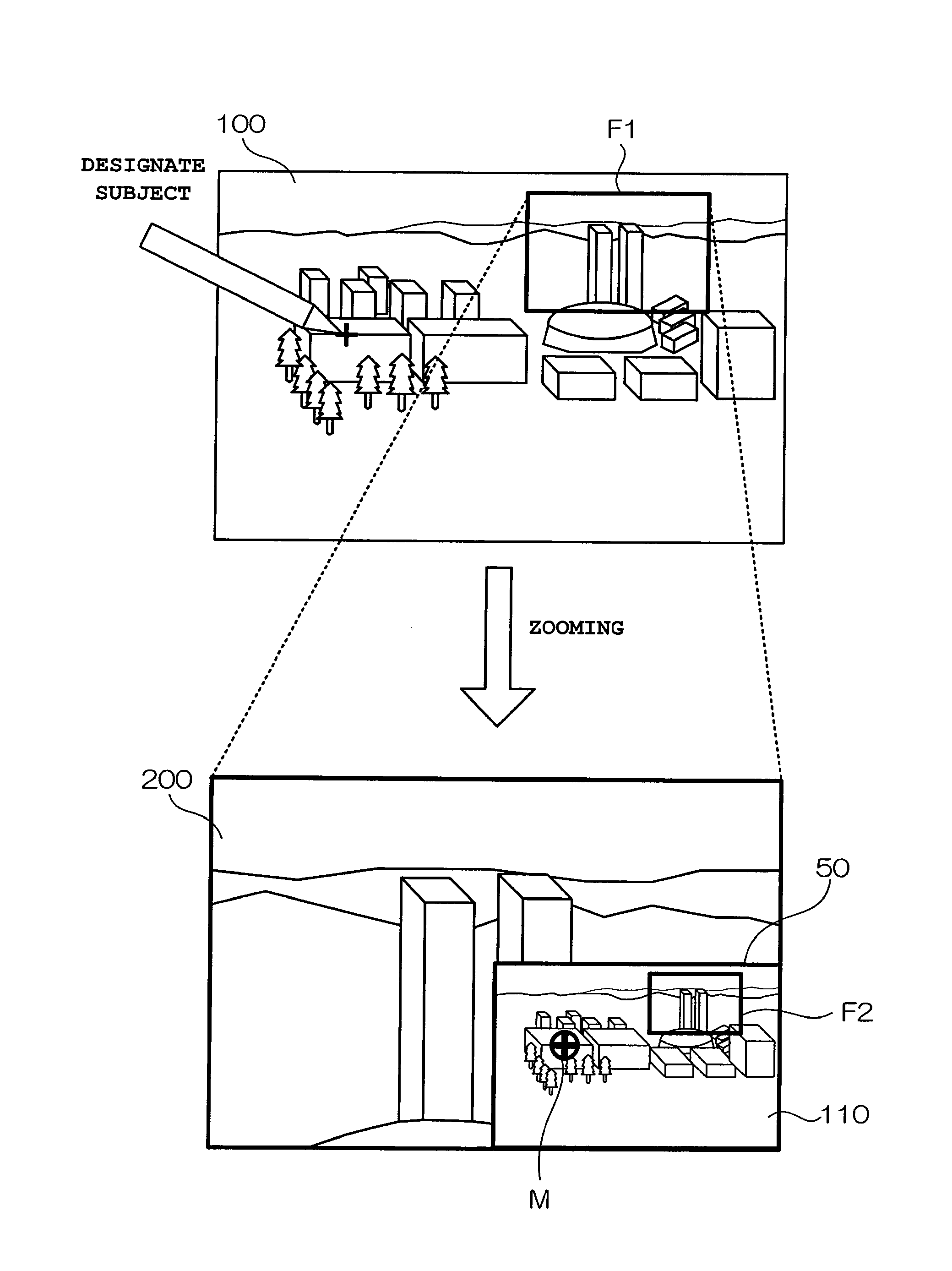
a technology of zoom function and imaging apparatus, which is applied in the field of imaging apparatus having a zoom function, can solve the problems of no longer being able to see the subject, the camera cannot be mounted with a high-magnification zoom lens, and the camera loses sight of the subject, so as to facilitate the confirmation of an imaging subject, shorten the battery life, and reduce the effect of product siz

Active Publication Date: 2010-09-30
CASIO COMPUTER CO LTD
View PDF47 Cites 26 Cited by
  • Summary
  • Abstract
  • Description
  • Claims
  • Application Information

AI Technical Summary

Benefits of technology

[0009]The present invention has been conceived to solve the above-described problems. An object of the present invention is to provide an imaging apparatus and an imaging method which enable the user to easily confirm...

Problems solved by technology

Conventionally, there has been a problem in a camera mounted with a high-magnification zoom lens having, for example, a magnification of 10× or 20×.
As a result, the subject is no longer included in the coverage range and the camera loses sight of the subject.
Even when an attempt is made to once again place the subject within the coverage range, the further the zoom lens is positioned towards the telephoto side, the mo...

Method used


Image

  • Imaging apparatus having a zoom function
  • Imaging apparatus having a zoom function
  • Imaging apparatus having a zoom function

Examples


Embodiment Construction

[0022]The present invention will hereinafter be described in detail with reference to the preferred embodiments shown in the accompanying drawings.

A. Configuration According to the Embodiment

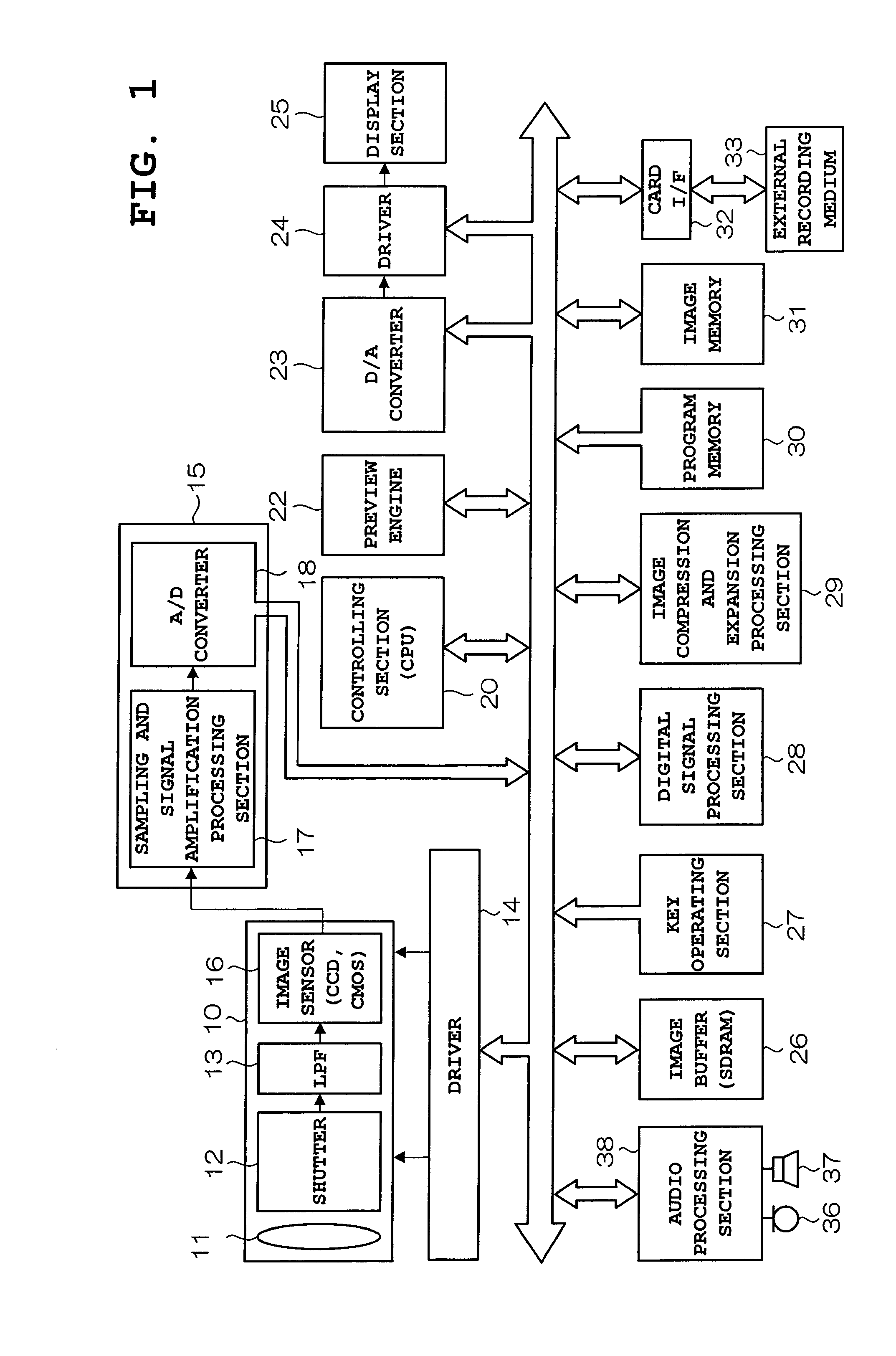
[0023]FIG. 1 is a block diagram showing a configuration of a digital camera (imaging apparatus) according to an embodiment of the present invention.

[0024]In FIG. 1, an image acquiring section 10 (imaging unit) includes a lens 11, a shutter 12, a low-pass filter (LPF) 13, and an image sensor (charge-coupled device [CCD] or complementary metal-oxide semiconductor [CMOS]) 16. The lens 11, which is an ordinary optical lens constituted by a lens group in which aspherical lenses are stacked, is capable of optical zoom. The zoom magnification ratio of the lens 11 can be arbitrarily changed in accordance with an instruction given by user operation. The shutter 12 is a so-called mechanical shutter operated by a driver 14 driven by a controlling section 20 when a shutter button is operated. Depending on t...


PUM


Abstract

In a digital camera, when the shutter is half-depressed, a controlling section 20 sequentially acquires current through-images imaged by an image acquiring section 10 which are wide-angle images imaged before zooming. Then, when a zoom operation is performed, the controlling section 20 holds a wide-angle image acquired at that point as a guidance image. Next, when the zoom magnification exceeds a predetermined magnification (for example, 3×), the controlling section 20 displays in a display section 25 the guidance image (wide-angle: low magnification) imaged before the zoom operation with a telephoto image imaged after the zoom operation. At the same time, a position corresponding to the current telephoto image is displayed to be identifiable within the guidance image. As a result, an imaging subject is easily confirmed when zooming is performed from wide-angle imaging to telephoto imaging.

Description

CROSS-REFERENCE TO RELATED APPLICATION[0001]This application is based upon and claims the benefit of priority from the prior Japanese Patent Application No. 2009-078176, filed Mar. 27, 2009, the entire contents of which is incorporated herein by reference.BACKGROUND OF THE INVENTION[0002]1. Field of the Invention[0003]The present invention relates to an imaging apparatus having a zoom function, a controlling method thereof, and a control program (recording medium) thereof.[0004]2. Description of the Related Art[0005]Conventionally, there has been a problem in a camera mounted with a high-magnification zoom lens having, for example, a magnification of 10× or 20×. In shooting a subject from a distance with the zoom lens positioned at the wide-angle end side, the coverage range tends to shift as the zoom lens zooms in toward the telephoto side because of camera shake. As a result, the subject is no longer included in the coverage range and the camera loses sight of the subject.[0006]Ev...

Claims


Application Information

Patent Timeline
IPC IPC(8): H04N5/262
CPCH04N5/232H04N5/23293H04N5/23216H04N23/62H04N23/69
Inventor KUROKAWA, TOMOYASU
Owner CASIO COMPUTER CO LTD
Why Eureka
Try Eureka