Removably mountable fiber optic terminal

a fiber optic terminal and removable technology, applied in the field of fiber optic terminals, can solve the problems of limited space in a data center or central office for equipment racks, limited availability of space in a data center or central office, and high cost,

Active Publication Date: 2010-09-30
CORNING OPTICAL COMM LLC
View PDF103 Cites 51 Cited by
  • Summary
  • Abstract
  • Description
  • Claims
  • Application Information

AI Technical Summary

Benefits of technology

[0006]Embodiments disclosed in the detailed description include a zero-U, high-density fiber optic terminal for data centers and central offices. The terminal may be used for optical fiber interconnection and/or optical fiber and fiber optic cable storage. The terminal is removably mountable to a cable tray above fiber optic equipment equipment, in a subfloor below fiber optic equipment or on a wall in proximity of fiber optic equipment. Additionally, the terminal may have an adapter panel with fiber optic adapters for optically connecting the optical fiber of a first fiber optic cable r

Problems solved by technology

However, available space in a data center or central office for equipment racks may be limited and/or very expensive.
Therefore, a c

Method used


Image

  • Removably mountable fiber optic terminal
  • Removably mountable fiber optic terminal
  • Removably mountable fiber optic terminal

Examples


Embodiment Construction

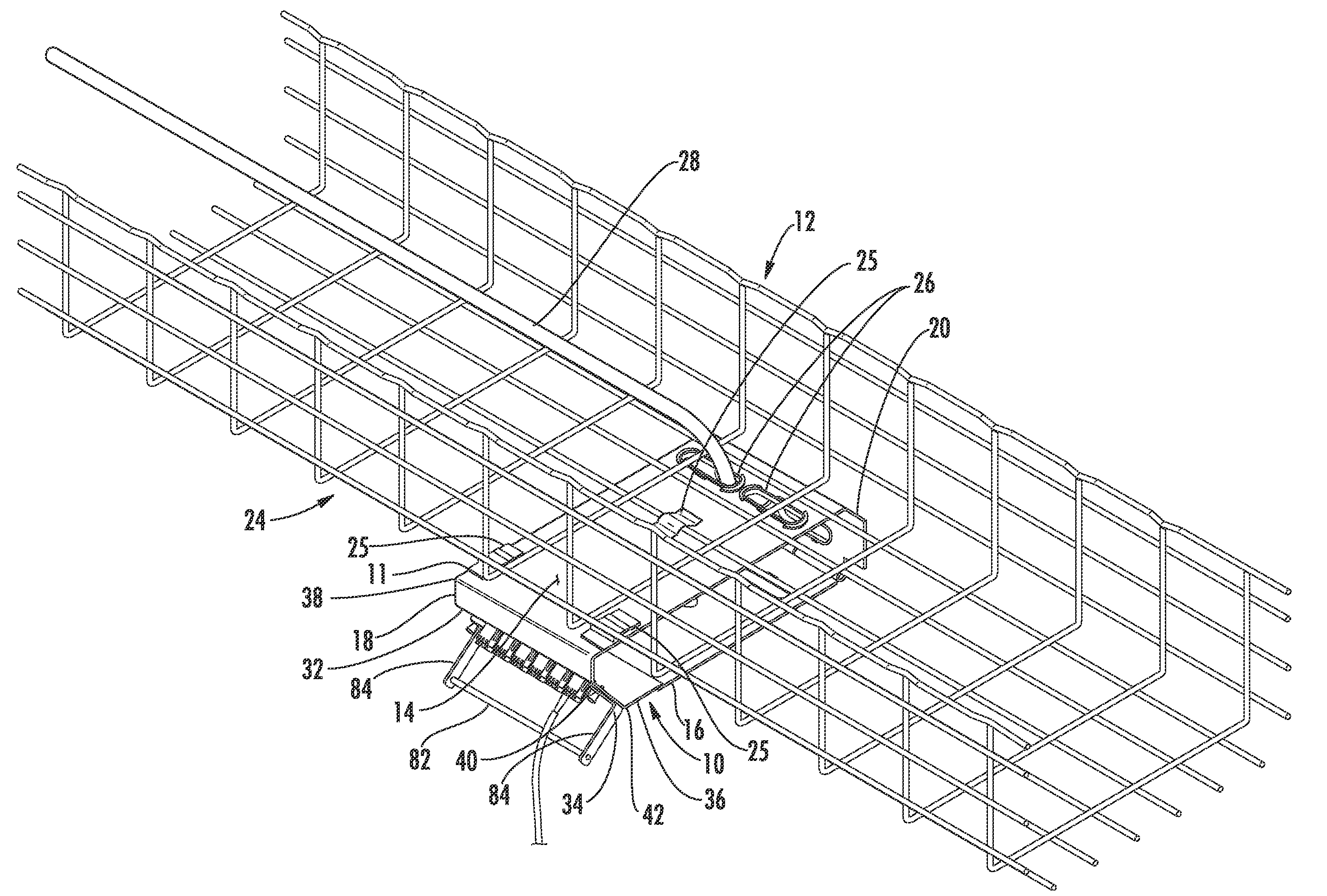
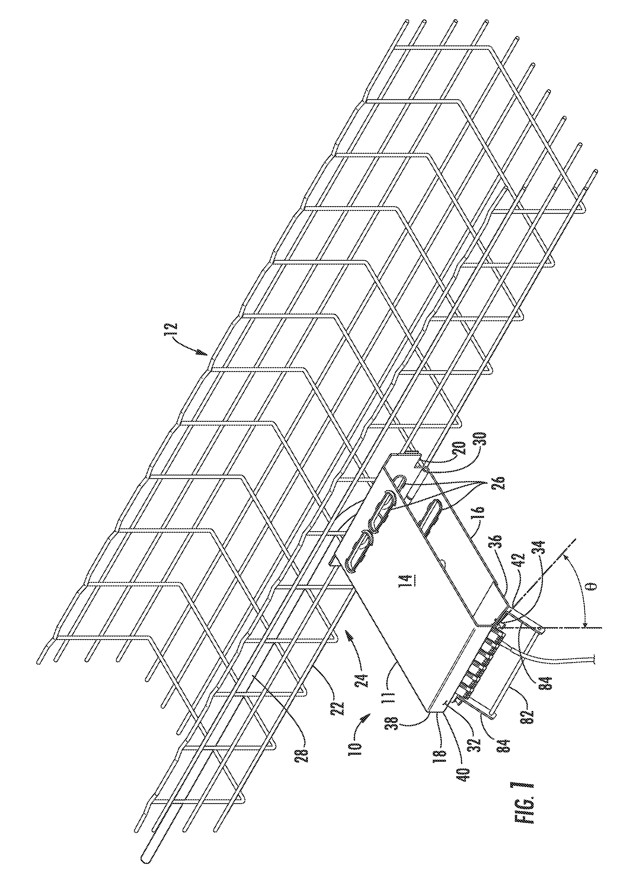
[0015]Reference will now be made in detail to the embodiments, examples of which are illustrated in the accompanying drawings, in which some, but not all embodiments are shown. Indeed, the embodiments may be embodied in many different forms and should not be construed as limited to the embodiments set forth herein; rather, these embodiments are provided so that this disclosure will satisfy applicable legal requirements. Whenever possible, like reference numbers will be used to refer to like components or parts.

[0016]To optimize space management in a central office or data center, it is desirable to develop ways in which some fiber optic equipment or components may be located, positioned, and / or mounted in the data center or central office so as not to occupy any equipment rack space. Typically in such case, such equipment or component may be referred to as being “zero-U,” which means that they take up zero or no units of space in the equipment rack. Further space management optimiza...


PUM


Abstract

A zero-U, high-density fiber optic terminal for data centers and central offices is disclosed. The terminal may be used for optical fiber interconnection and/or optical fiber and fiber optic cable storage. The terminal is removably mountable to a cable tray above fiber optic equipment, in a subfloor below fiber optic equipment or on a wall in proximity of fiber optic equipment. Additionally, the terminal may have an adapter panel with fiber optic adapters for optically connecting the optical fiber of a first fiber optic cable received from the cable tray and the optical fiber of a second fiber optic cable. The second fiber optic cable is intended to extend to the fiber optic equipment. The adapter panel and the fiber optic adapters are angled generally in the direction in which the second fiber optic cable is intended to extend. Angling the fiber optic adapters in this manner accommodates routing of second fiber optic cable, and provides ease of access to the fiber optic adapters for connecting and disconnecting fiber optic connectors and to slack storage components for cable management mounted in the terminal.

Description

CROSS-REFERENCE TO RELATED APPLICATIONS[0001]This application claims the benefit of priority to U.S. Provisional Patent Application No. 61 / 165,272 filed on Mar. 31, 2009 the contents of which are relied upon and incorporated herein by reference in their entirety.BACKGROUND[0002]The technology of the disclosure relates to a fiber optic terminal, and more particularly to a fiber optic terminal having a housing that is removably mountable to a cable tray, beneath a sub-floor, or to a wall to provide a zero-U installation in a data center or a central office.[0003]Benefits of optical fiber use include extremely wide bandwidth and low noise operation. Because of these advantages, optical fiber is increasingly being used for a variety of applications, including but not limited to broadband voice, video, and data transmission. Fiber optic networks employing optical fiber are being developed and used to deliver voice, video, and data transmissions to subscribers over both private and public...

Claims


Application Information

Patent Timeline
IPC IPC(8): G02B6/00
CPCG02B6/4459G02B6/4453
Inventor COWEN, ANDREW P.MURES, MARCEL G.PREVRATIL, KARYNE P.WEEKS, JOSEPH A.
Owner CORNING OPTICAL COMM LLC
Why Eureka
Try Eureka