Air pump for air mattress

Inactive Publication Date: 2010-09-30
DONGGUAN TIGER POINT METAL & PLASTIC PRODS
View PDF6 Cites 23 Cited by
  • Summary
  • Abstract
  • Description
  • Claims
  • Application Information

AI Technical Summary

Benefits of technology

[0016]Differing from conventional air pump for an air mattress, the present invention mainly employs the actuating mechanism to move the slider and the sloping partition of the slider to prop up the air valve so as to switch to different operation mode. Structurally, the present invention ha

Problems solved by technology

Despite the inflating and deflating features owned by the conventional air pump, there are still many problems of the conventional air pump yet to be improved, especially p

Method used


Image

  • Air pump for air mattress
  • Air pump for air mattress
  • Air pump for air mattress

Examples


Embodiment Construction

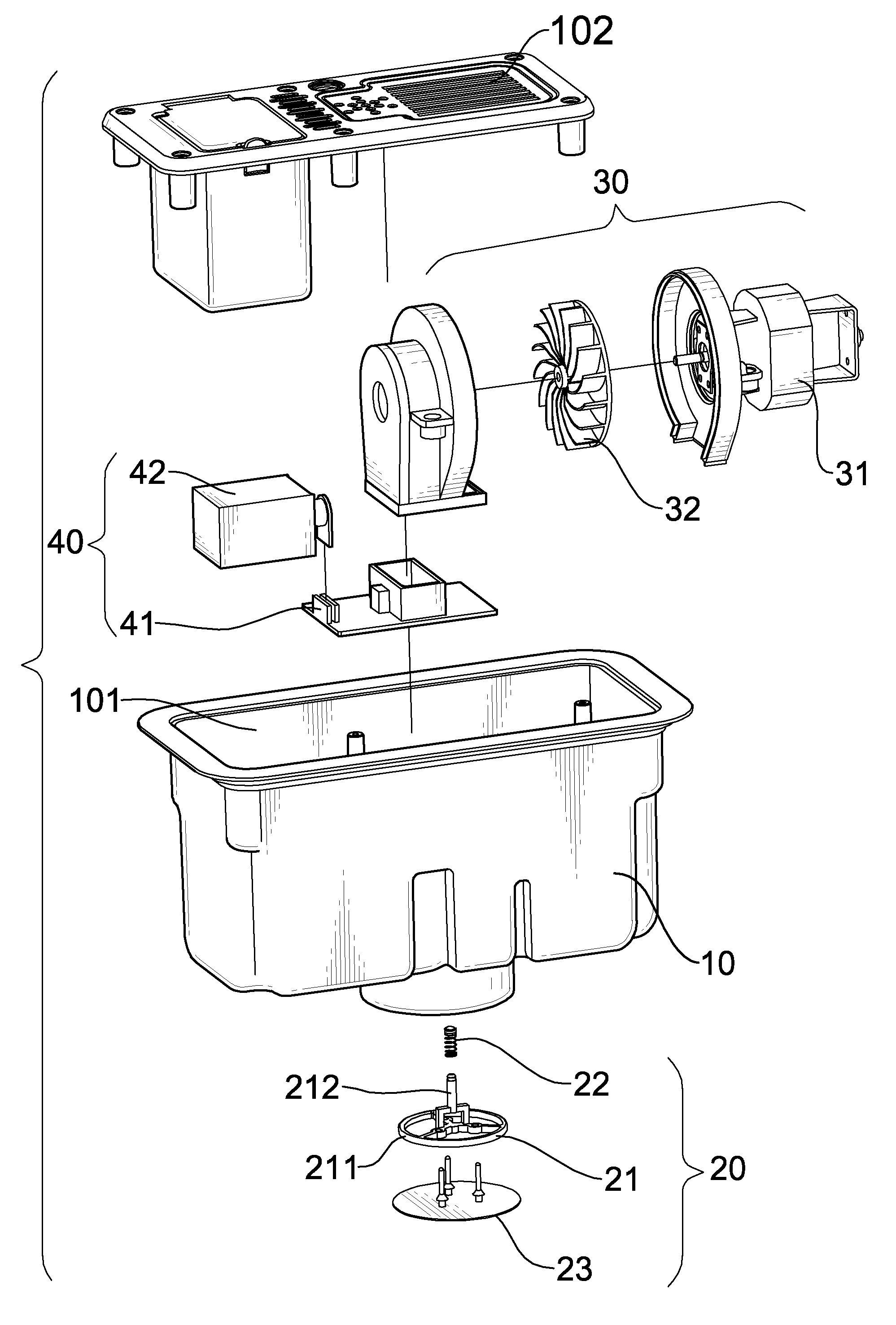
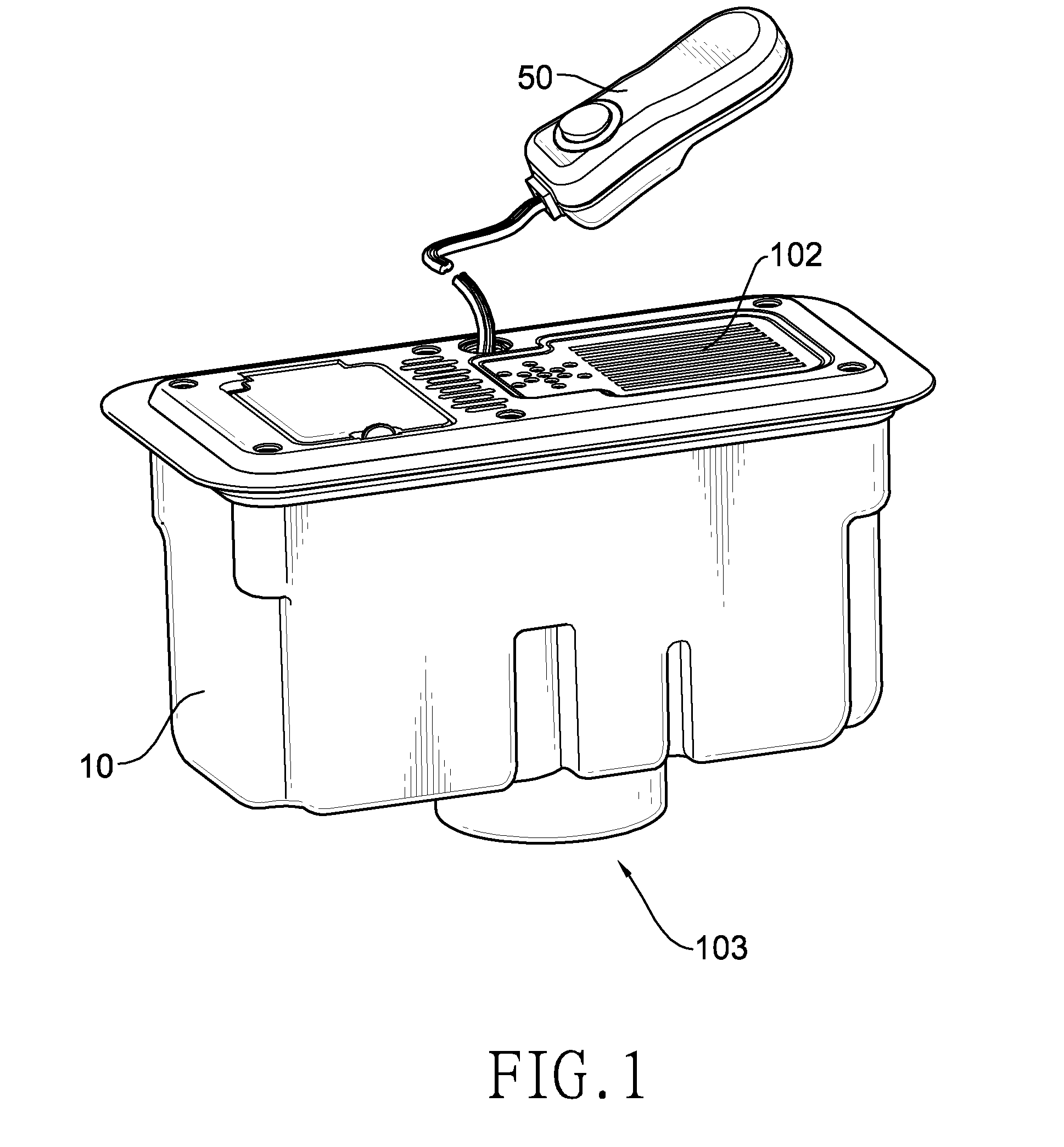
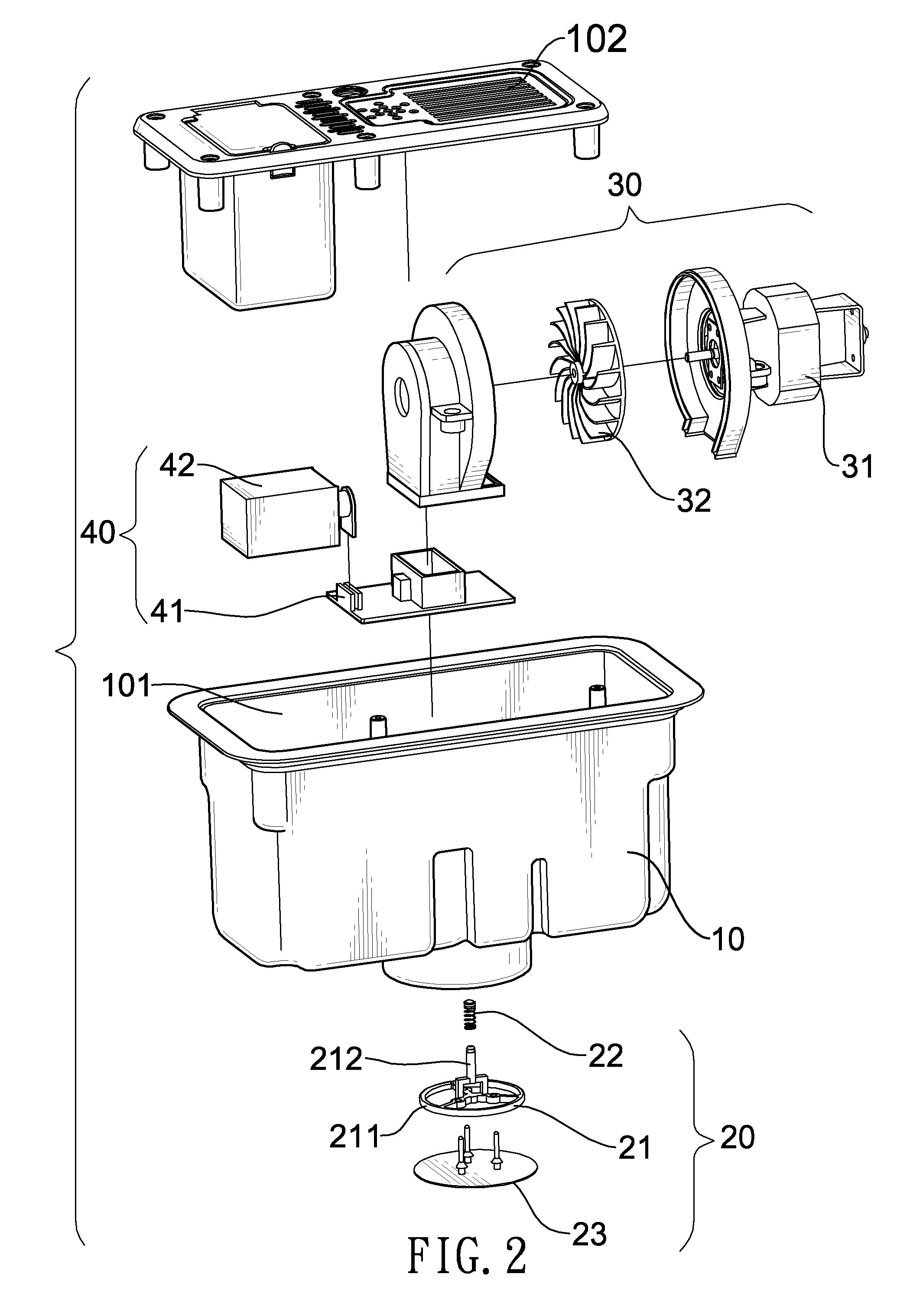
[0027]With reference to FIGS. 1 to 6, a first embodiment of an air pump for an air mattress has a housing (10), a chamber (101), a first air vent (102), a second air vent (103), an air valve (20), a blower (30) and an air direction switcher (40).

[0028]The chamber (101) is defined inside the housing (10). The first air vent (102) is mounted on a top of the housing (10), takes the form of a plurality of parallel slots or round holes formed through the top of the housing (10), communicates with the chamber (101), and is exposed beyond an air mattress in which the air pump is mounted. The second air vent (103) is mounted on a bottom of the housing (10) opposite to the top of the housing (10), and communicates with the chamber (101) and an inner space of the air mattress. The first air vent (102) and the second air vent (103) may be arranged to directly align to each other. The air valve (20) is mounted at the second air vent (103) to block or open the second air vent (103). The blower (...


PUM


Abstract

An air pump for an air mattress has a housing, a first air vent and a second air vent respectively mounted on a top and a bottom of the housing, a chamber, a blower and an air direction switcher mounted in the chamber, an actuating mechanism, and an air valve. A slider in the air direction switcher is moved by operating the actuating mechanism being a solenoid valve or a knob gear and a follower. The air valve is propped up by a sloping partition of the slider to open the second air vent. Given the structure of the air pump, the first and second air vents are flexibly arranged and can be directly aligned with each other. Therefore, the air path is shortened to inflate and deflate more rapidly and more efficiently.

Description

BACKGROUND OF THE INVENTION[0001]1. Field of the Invention[0002]The present invention is related to an air pump for an air mattress, and more particularly to an air pump for rapidly inflating and deflating an air mattress.[0003]2. Description of the Related Art[0004]Air pumps are critical parts of inflatable air mattresses. Usually, air pumps are mounted inside the inflatable air mattresses for inflating and deflating air mattresses and also maintaining the pressure therein. As inflatable air mattresses can be used or stored by inflating and deflating it, they are widely used for traveling and going camping or providing a temporary bed.[0005]A conventional air pump for an air mattress has a housing, and a motor, an impeller, a solenoid valve, a slider and an air valve mounted inside the housing. An air vent and an air slot are respectively mounted on a side and a bottom of the housing. The air valve seals the air vent, and the slider corresponds to the air slot. The air valve is con...

Claims


Application Information

Patent Timeline
IPC IPC(8): F04B19/04F04B17/04
CPCF04D29/602A47C27/082F04D29/503F04D25/084
Inventor TSAI, CHUN-CHUNG
Owner DONGGUAN TIGER POINT METAL & PLASTIC PRODS
Why Eureka
Try Eureka