
Flanged interbody fusion device

a fusion device and interbody technology, applied in the field of spinal fixation systems and methods, can solve the problems of degenerative changes in the bones, spine instability, pain and instability,

Active Publication Date: 2010-09-30
SPINAL ELEMENTS INC
View PDF101 Cites 182 Cited by
  • Summary
  • Abstract
  • Description
  • Claims
  • Application Information

AI Technical Summary

Benefits of technology

[0016]The above embodiments and methods o

Problems solved by technology

Advancing age, as well as injury, can lead to degenerative changes in the bones, discs, joints and ligaments of the spine, producing pain and instability.
Spine instability may result from causes such as fracture, scoliosis and spondylolisthesis, where one or more vertebrae move in a forward direction relative to the other vertebrae.
Early fixation devices tended to be applicable only to long bone injuries with only limited uses for lower lumbar spinal injuries and disorders.
In existing spinal fusion implants there have also been problems with loosening and backing out of screws, especially in the cervical vertebrae where the screws can back out into the patient's throat area.
Backout is the exhibited tendency of bone screws, which affix the bone plate to the bone(s), to loosen with respect to both the plate and bone, resulting in poor fixation, fusion and ultimately, healing.
This results in the bone plate being poorly fixed in place thus becoming devoid of its fixation capabilities.
While such loosening can be benign if limited in scope, it can lead to complications such as complete failure of the fixation device or incomplete bone fusion.
While a locking screw or collar can alleviate backout, successful use of such locking device systems in the anterior cervical spine is particularly difficult because of anatomic constraints.
Systems using multiple types of screws or collars to hold the bone screw in place are difficult to deploy within the confines of a small operating area available at the cervical spine.
Furthermore, due to the small operating area, the surgeon implanting the device has great difficulty determining if the device is properly deployed.
Thus, while current systems can help reduce instances of backout, their complex nature makes proper deployment very difficult and increases the chance of surgical error.
Implants adapted for use in the lumbar spine and the thoracic spine become much less usable in the cervical spine because of differences in anatomy.
Because of this limitation in existing spinal fixation devices, treatment of spinal disorders may be suboptimal because disease in adjacent vertebrae cannot be treated adequately.

Method used


Image

  • Flanged interbody fusion device
  • Flanged interbody fusion device
  • Flanged interbody fusion device

Examples


Embodiment Construction

A. Anatomy of the Spine

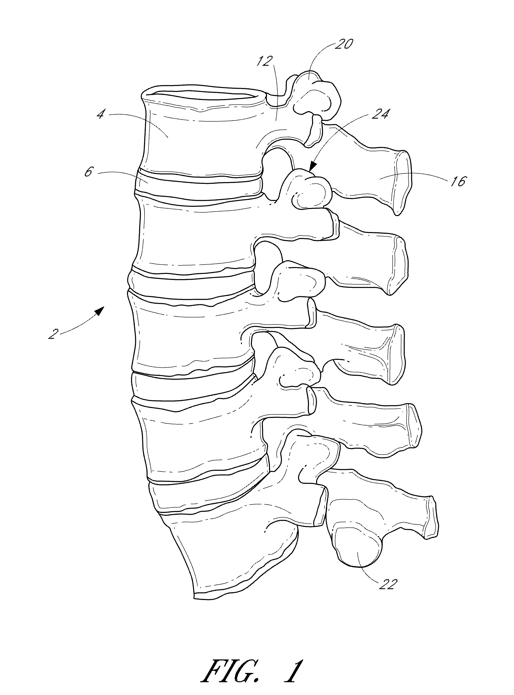
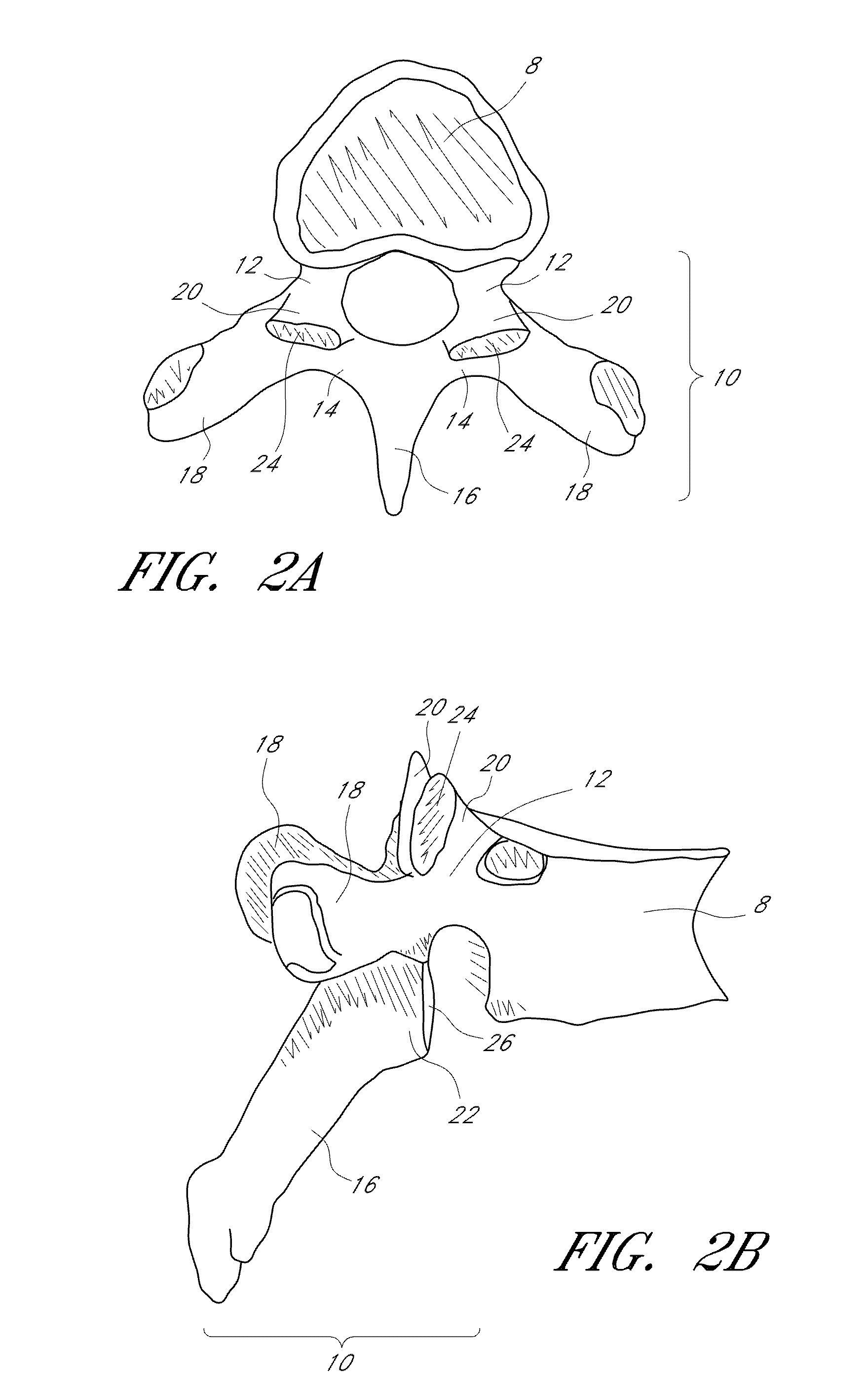
[0029]As shown in FIG. 1, the vertebral column 2 comprises a series of alternating vertebrae 4 and fibrous discs 6 that provide axial support and movement to the upper portions of the body. The vertebral column 2 typically comprises thirty-three vertebrae 4, with seven cervical (C1-C7), twelve thoracic (T1-T12), five lumbar (L1-15), five fused sacral (S1-S5) and four fused coccygeal vertebrae. FIGS. 2A and 2B depict a typical thoracic vertebra. Each vertebra includes an anterior body 8 with a posterior arch 10. The posterior arch 10 comprises two pedicles 12 and two laminae 14 that join posteriorly to form a spinous process 16. Projecting from each side of the posterior arch 10 is a transverse 18, superior 20 and inferior articular process 22. The facets 24, 26 of the superior 20 and inferior articular processes 22 form facet joints 28 with the articular processes of the adjacent vertebrae.

[0030]The typical cervical vertebrae 30, shown in FIG. 3, differ from t...


PUM


Abstract

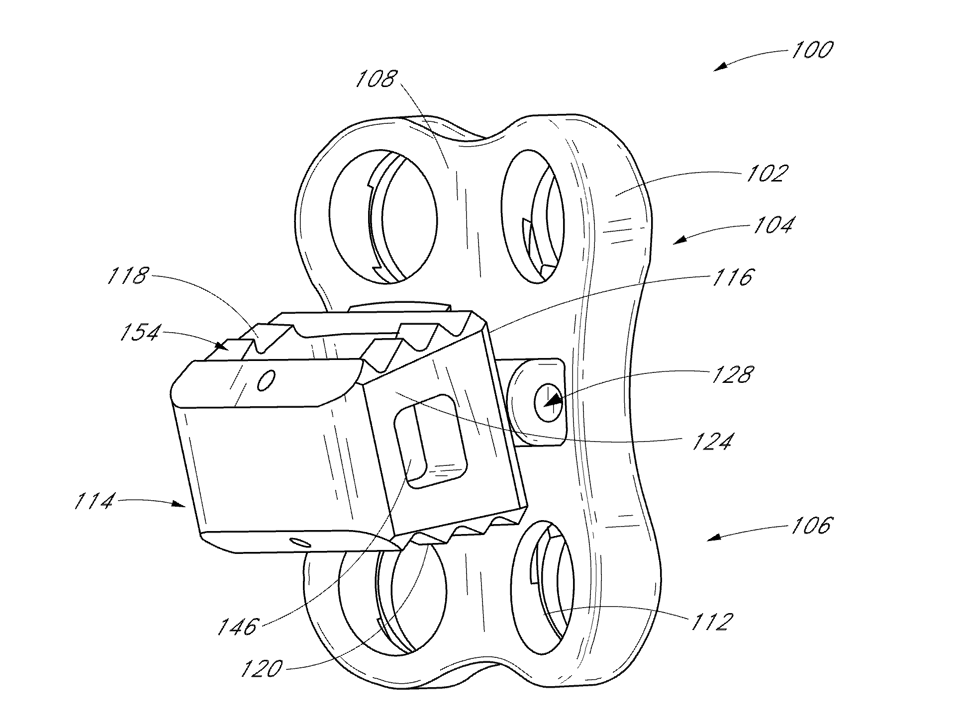
Methods and devices are disclosed for treating the vertebral column. An implant for treating the spine is provided comprising at least two articulations between the spacer and the bone facing surface of the fixation plate. Another implant for treating the spine is also provided, comprising two or more fixation plates attached to a spacer with two or more articulations, wherein the fixation plates are independently movable.

Description

CROSS-REFERENCE TO RELATED APPLICATIONS[0001]The present application claims priority under 35 U.S.C. §119(e) to U.S. Provisional Application No. 61 / 164,029 filed on Mar. 27, 2009, the disclosure of which is incorporated by reference herein in its entirety.BACKGROUND OF THE INVENTION[0002]1. Field of the Invention[0003]This invention relates generally to systems and methods for performing spinal fixation and, in particular, to interbody spacer devices.[0004]2. Description of the Related Art[0005]Advancing age, as well as injury, can lead to degenerative changes in the bones, discs, joints and ligaments of the spine, producing pain and instability. Under certain circumstances, alleviation of the problems can be provided by performing spinal fusion. Spinal fusion is a surgical technique where two or more vertebrae of the spinal column are fused together to eliminate the motion between the fused vertebrae. Spinal fusion is used to treat conditions where the spine exhibits instability. S...

Claims


Application Information

Patent Timeline
IPC IPC(8): A61F2/44A61B17/70A61B17/88
CPCA61B17/7059A61F2002/30777A61F2/447A61F2002/2835A61F2002/30062A61F2002/3008A61F2002/3037A61F2002/30392A61F2002/30397A61F2002/30398A61F2002/30563A61F2002/30578A61F2002/30624A61F2002/30637A61F2002/30649A61F2002/30785A61F2002/30789A61F2002/30841A61F2002/30904A61F2002/3092A61F2002/30983A61F2002/4475A61F2210/0004A61F2220/0025A61F2220/0033A61F2250/0098A61F2310/00011A61F2310/00023A61F2310/00179A61F2310/00215A61F2310/00221A61F2310/0052A61B17/8047A61F2/3094A61F2002/30593
Inventor BLAIN, JASONHILDEBRAND, BRYANKOVACH, ERIC
Owner SPINAL ELEMENTS INC
Learn More