Intake nozzle for a pump

a technology for pumping and nozzles, which is applied in the direction of flexible pipes, rigid pipes, pipe supports, etc., can solve the problems of pump losing suction, low capacity, and not allowing the pump to pump the fluid level down, so as to reduce the unit pressure drop, reduce the pressure at the suction, and reduce the effect of pressur

Inactive Publication Date: 2010-10-07
KOCH EDWARD JOHN
View PDF8 Cites 19 Cited by
  • Summary
  • Abstract
  • Description
  • Claims
  • Application Information

AI Technical Summary

Benefits of technology

[0020]Preferably the annular gap is located at a diameter which is at least double the diameter of the bottom mouth. In this way the liquid flow gradually and smoothly changes in direction from the horizontal direction under the nozzle surface into the vertical direction as it passes through the bottom mouth. It will be appreciated that the larger the radius of the device, the more efficient it will be at reducing the gap so as to reduce the velocity and thus the likelihood of air breakthrough at the gap. Different models can be provided for different pump sizes with different gaps and different overall diameters.
[0024]This leads the liquid away from the nozzle with minimum direction changes, although the duct may include an elbow which changes the direction to a horizontal direction across the surface. The duct may contain a screen type filter to prevent debris entering the pump if the device loses contact with the surface while the pump is operating.
[0027]Thus the arrangement as described hereinafter provides a new pump suction device. The device as described may have one or more of the following features and advantages:
[0031]The pump works by reducing the pressure at the suction. This reduced pressure causes the fluid to flow to the pump. By increasing the flow area at the outside edge of the gap (above the TFA), this device reduces the unit pressure drop at the outside edge of the nozzle. This is why the velocity of the fluid into the edge of the device is lower than the velocity through the suction hose. This low velocity reduces the pump suction so as to reduce the possibility of air breakthrough and is a key feature in allowing the device to lower the fluid level as close to the floor as is possible.

Problems solved by technology

However these are generally of low capacity and are unsuitable in situations where large volumes of liquid are to be pumped.
The problem with the strainer device is that it does not allow the pump to pump the fluid level down to the floor.
Because of the design of the strainer, the pump loses suction while there is still a significant amount of water to be pumped from a flat surface.
This also happens when pumping without the strainer device.

Method used


Image

  • Intake nozzle for a pump
  • Intake nozzle for a pump
  • Intake nozzle for a pump

Examples


Embodiment Construction

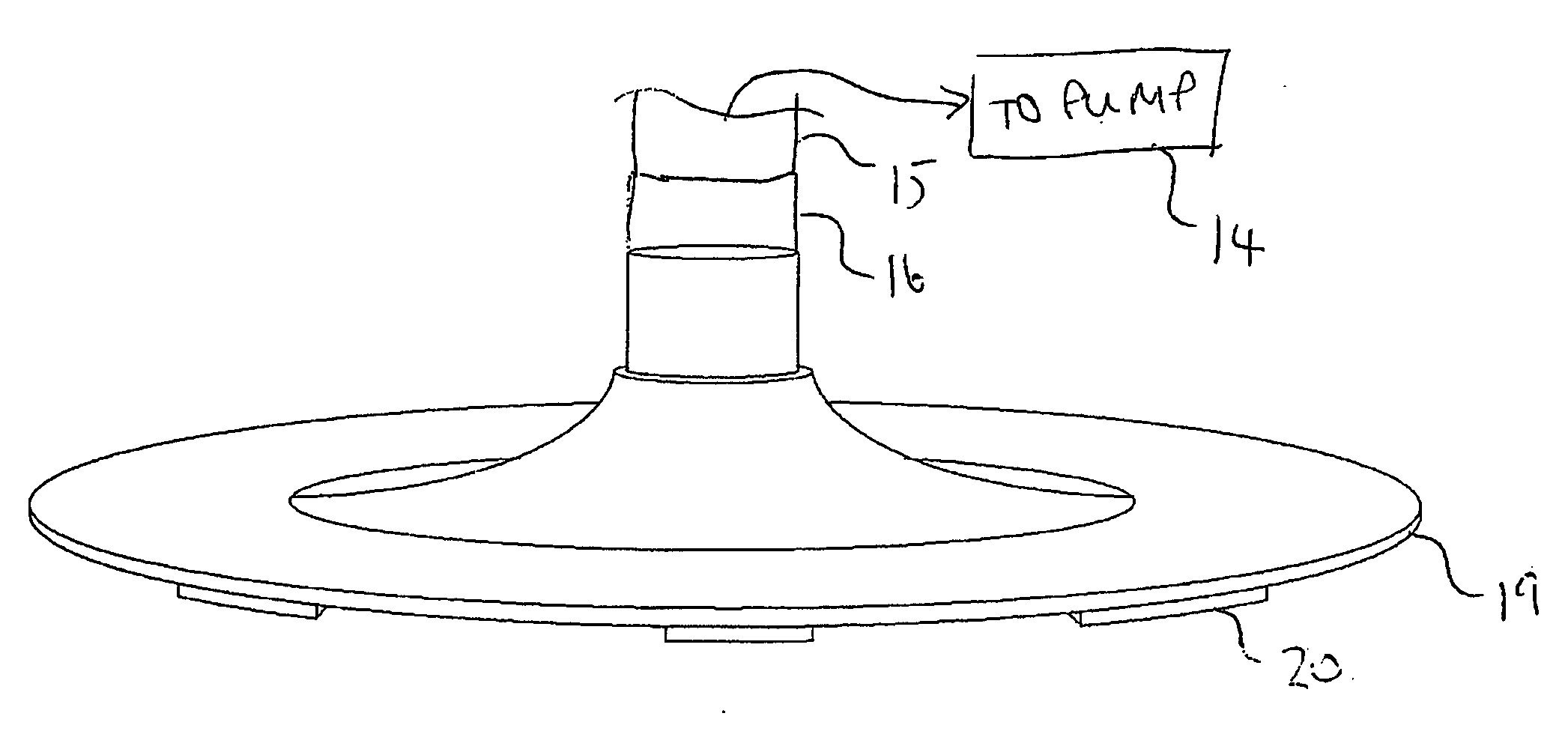
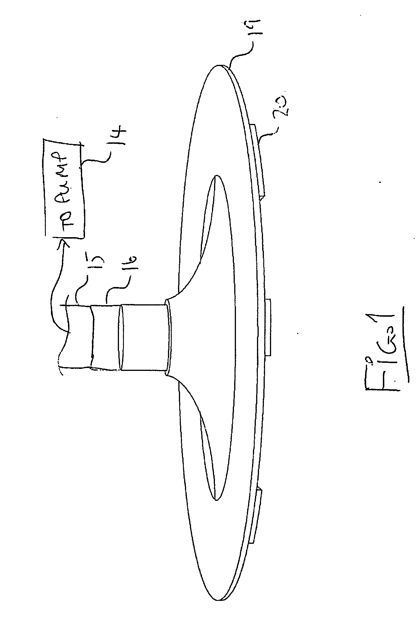
[0037]The embodiment of the intake nozzle 10 shown in the drawings is arranged to sit on a flat surface 13 to remove liquid from the surface by the suction of the pump 14 which has an intake line 15 connected by a coupling 16 to the nozzle.

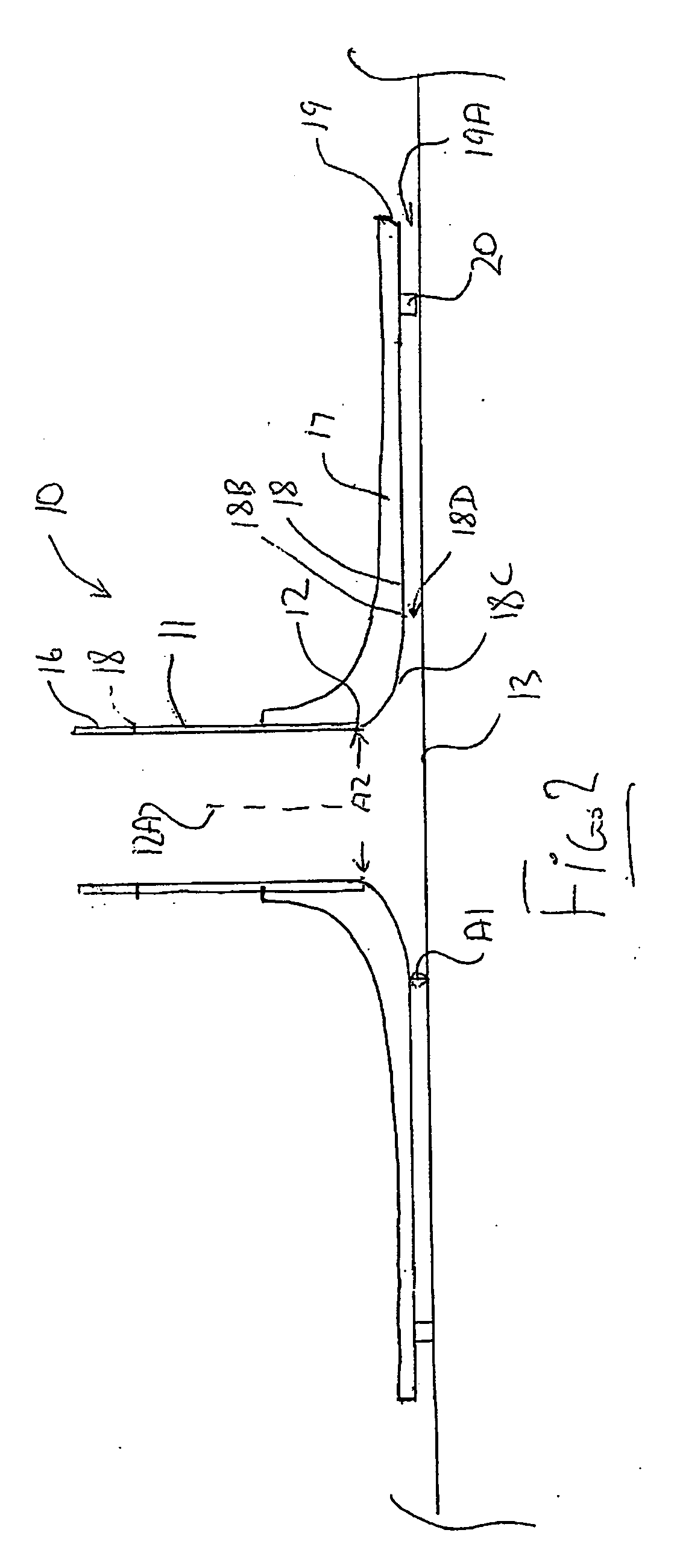
[0038]The nozzle comprises a cylindrical duct portion 11 and a plate member 17 surrounding the duct portion. The duct portion stands vertically upwardly and defines a circular bottom mouth 12 surrounding a central upstanding axis 13 of the duct portion and a circular upper end 18 which connects to the circular pipe 15 with a common inner diameter through the connection and to the pump.

[0039]The bottom mouth 12 faces downwardly toward the upwardly facing flat surface 13 from which liquid is to be drawn into the mouth.

[0040]The plate member 17 surrounding the bottom mouth and defines a downwardly facing nozzle surface 18 facing the flat surface 13, so that the liquid is drawn between the flat surface and the downwardly facing nozzle surface to flow ...


PUM


Abstract

An intake nozzle for the inlet pipe of a pump has a vertical duct with a downwardly facing mouth and a surrounding disk shaped intake portion with a bottom surface which faces a flat surface such as a floor or tank bottom to take liquid from the floor down to a shallow depth. The bottom surface is shaped with a flat outer part and an upwardly and inwardly curved inner part converging to the mouth. The surface is shaped and spaced from the flat surface with annular areas defined therebetween so that the liquid enters the peripheral edge slowly and accelerates up to an inner edge of the flat portion and then remains at constant velocity from the inner edge of the flat portion through the mouth and the pipe to the intake of the pump.

Description

[0001]This invention relates to an intake nozzle for a pump for removing liquid from a surface.BACKGROUND OF THE INVENTION[0002]It is commonly necessary to pump liquid from a surface in the event of a flood or spill, or from the bottom surface of a tank or containment area to remove the fluid.[0003]Submersible sump pumps are available which sit flat on the surface and can pump down to a relatively low liquid surface level. However these are generally of low capacity and are unsuitable in situations where large volumes of liquid are to be pumped.[0004]A larger volume of flow can be generated using a remote pump with an intake line leading to the surface. Typically such pumps are provided with a generally conical strainer device that fits on the end of the suction line to prevent debris from entering the pump suction. The problem with the strainer device is that it does not allow the pump to pump the fluid level down to the floor. The pump loses suction leaving a significant standing ...

Claims


Application Information

Patent Timeline
Patent Type & Authority Applications(United States)
IPC IPC(8): F16L3/00
CPCF04D29/708
Inventor KOCH, EDWARD JOHN
Owner KOCH EDWARD JOHN
Why Eureka
Try Eureka