Pneumatic radial tire

a pneumatic radial tire and radial tire technology, applied in the direction of non-skid devices, vehicle components, transportation and packaging, etc., can solve the problems of impaired handling stability of pneumatic radial tires, too high stiffness to allow the necessary deformation of the sidewall portion, and vehicle may become less stable, etc., to achieve the effect of improving handling stability

Inactive Publication Date: 2010-10-07
BRIDGESTONE CORP
View PDF16 Cites 7 Cited by
  • Summary
  • Abstract
  • Description
  • Claims
  • Application Information

AI Technical Summary

Benefits of technology

[0026]A pneumatic radial tire to be provided according to the aspects of the invention is capable of: securing sufficient drainage

Problems solved by technology

However, the above-described pneumatic radial tire has the following problem.
Consequently, the handling stability of such pneumatic radial tires is impaired while the vehicle is turning.
The solution, however, has the following problems.
In this case, the sidewall portion on the inner sid

Method used


Image

  • Pneumatic radial tire
  • Pneumatic radial tire
  • Pneumatic radial tire

Examples


embodiments

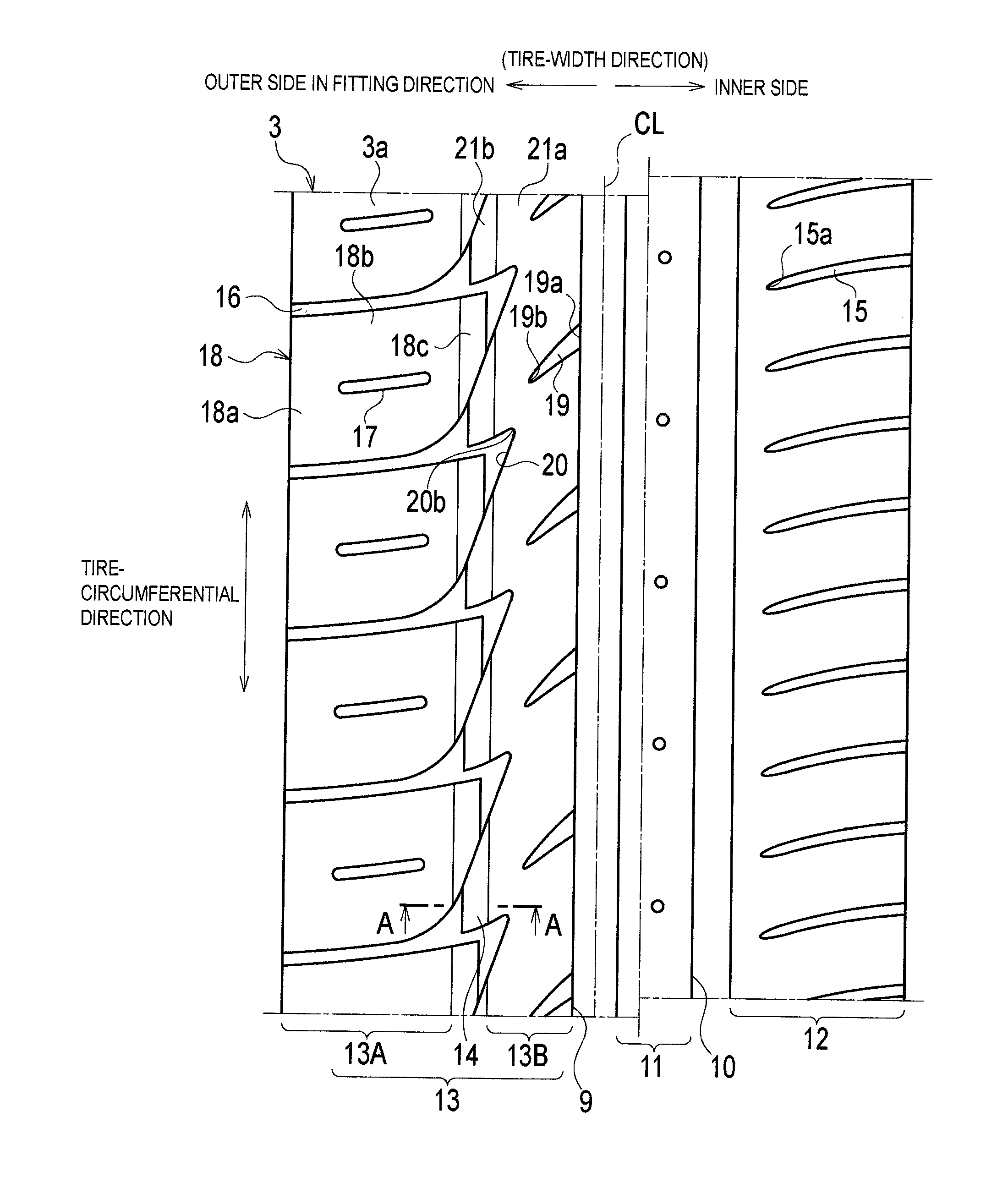
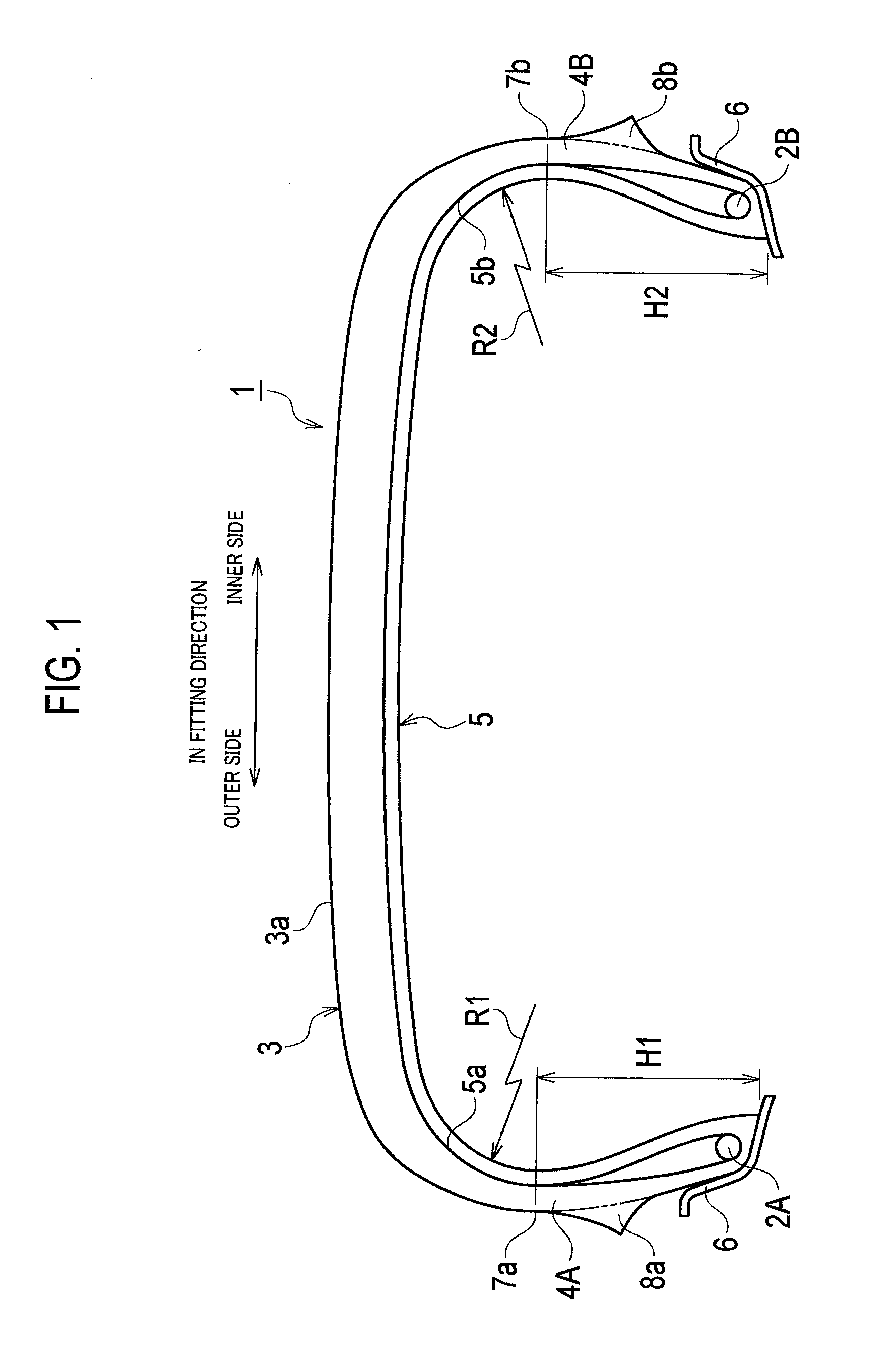
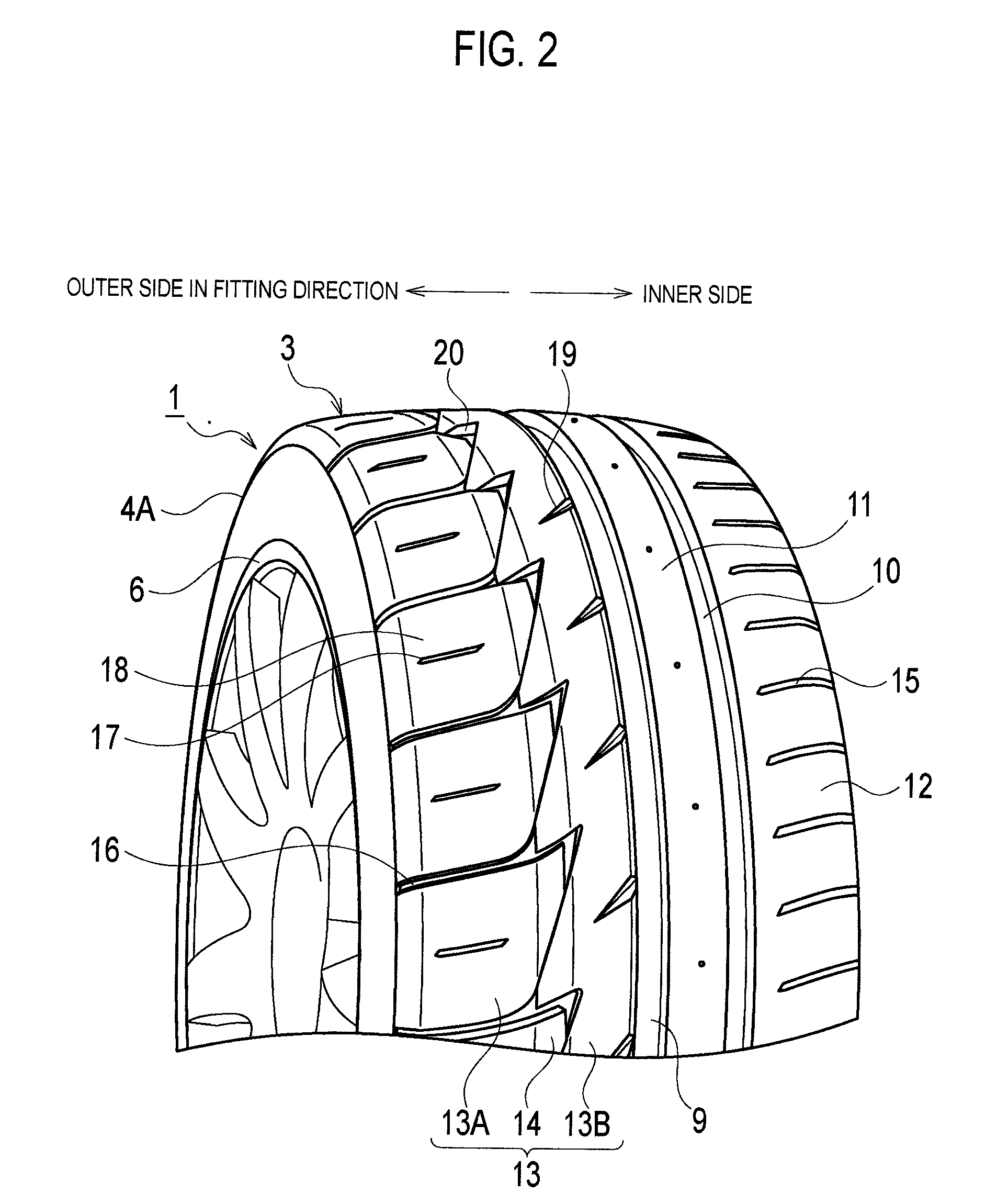
[0032]Some embodiments of the invention will be described below by referring to the drawings. Specifically, (1) overall configuration of a pneumatic radial tire; (2) detailed configuration of a tread surface portion; (3) detailed configuration of an outer-side lateral groove; and (4) advantageous effects are explained.

[0033]FIGS. 1 to 3 show an embodiment of the invention. FIG. 1 is a sectional view of a pneumatic radial tire inflated with air.

(1) Overall Configuration of Pneumatic Radial Tire

[0034]The overall configuration of the pneumatic radial tire will be described by referring to FIG. 1. As FIG. 1 shows, a pneumatic radial tire (hereafter, referred to as a “tire”) 1 of this embodiment includes a left-and-right pair of bead portions 2A and 2B, a tread portion 3, a left-and-right pair of sidewall portions 4A and 4B, and a carcass layer 5.

[0035]Each of the bead portions 2A and 2B has an annular shape. The tread portion 3 is located at the outer side, in a tire-radial direction, o...

examples

[0102]The width of and the area of the contact patch were measured using a pneumatic radial tire of Conventional Example and a pneumatic radial tire of Example. In addition, the average running speed was measured using a set of the pneumatic radial tires of each kind and the same test vehicle on a circuit-running test course. FIG. 5 shows various data on Example at the testing.

[0103]Each of the pneumatic radial tires used in the test had a size of 235 / 45R17. The surface curvature radius, measured in a section taken in the tire-width direction, of the case line of the carcass layer and the dimension, measured in the tire-width directions, from the bead portion to the widest convex portion were measured with each pneumatic radial tire inflated with air at 210 kPa. The measurement conditions were in conformity with 8.0J-17.

[0104]When the width of and the area of the contact patch of each tire were measured, the tire was inflated with air at 230 kPa and a load of 7.5 kN was applied to t...


PUM


Abstract

A pneumatic radial tire includes a pair of annular bead portions 2A, 2B, a tread portion 3 having a tread surface portion, a pair of sidewall portions 4A, 4B each connecting one of both end portions of tread portion 3 in tire-width directions and an outward end in the tire-radial direction of the corresponding one of the bead portions 2A, 2B, and a carcass layer 5 extending continuously across and through the bead portions 2A, 2B, the sidewall portions 3, and the tread portion 4A, 4B, the carcass layer 5 being configured to form a framework of the tire. Main grooves are formed respectively in a tire's equatorial portion including a center line in the tire-width directions of the tread portion and in a portion located closer to a vehicle-fitted inner side than the tire's equatorial portion is, each main groove extending continuously in a tire-circumferential direction of the tread portion, a land-portion block row in which a plurality of blocks are consecutively arranged in the tire-circumferential direction is formed in a portion of the tread portion located closer to a vehicle-fitted outer side than the tire's equatorial portion of the tire is, and in a section taken in the tire-width directions, a surface curvature radius of a case line of the carcass layer on the vehicle-fitted outer side is larger than a surface curvature radius of a case line of the carcass layer on the vehicle-fitted inner side while the tire is inflated with air.

Description

TECHNICAL FIELD[0001]The invention relates to a pneumatic radial tire in which a main groove extending in a tire-circumferential direction is formed in a tread portion.BACKGROUND ART[0002]Patent Document 1 discloses a pneumatic radial tire as related conventional art of this kind.[0003]In the pneumatic radial tire, at least one main groove extending in the tire-circumferential direction is formed in a portion on the outer side of the tread portion when the tire is fitted to the vehicle. In addition, of all the main grooves thus formed, the one that is closest to the tire equator line is set to have a relatively large width. Thereby the pneumatic radial tire can improve the drainage of the tread portion.[0004]In addition, in the pneumatic radial tire, at least two main grooves extending in the tire-circumferential direction are formed in portions located on the inner side of the tread portion when the tire is fitted to the vehicle. Of all the main grooves thus formed on this side, th...

Claims


Application Information

Patent Timeline
IPC IPC(8): B60C11/11B60C11/117
CPCB60C11/0309B60C11/032B60C2011/0383B60C11/1392B60C11/0304B60C11/13
Inventor ITO, TAKAHIRO
Owner BRIDGESTONE CORP
Why Eureka
Try Eureka