Felt for papermaking

a papermaking and felt technology, applied in the field of felt for papermaking, can solve the problems of insufficient effectiveness to prevent rewetting phenomenon, inability to easily set in a papermaking machine, and poor papermaking

Active Publication Date: 2010-10-07
ICHIKAWA ELECTRIC CO LTD
View PDF13 Cites 3 Cited by
  • Summary
  • Abstract
  • Description
  • Claims
  • Application Information

AI Technical Summary

Benefits of technology

[0015]Thus, it is an object of this invention to provide a papermaking felt which is capable of maintaining functions of a felt over a long period of time since beginning of use, i.e., a capability to rebound after compression, dewatering capability, and wet paper smoothing function, and which has flexibility so as to be easily set in a closed draw papermaking machine and is capable of preventing rewetting in the press portion thereof.
[0019]The felt of this invention is capable of maintaining functions as a felt, such as a capability to rebound after compression, dewatering capability, and wet paper smoothing function, over a long period of time since setting in and beginning of use, and has flexibility so as to be easily set in a closed draw papermaking machine, and is capable of restraining rewetting in the press portion.

Problems solved by technology

These changes have resulted in a problem that the felt is flattened under high pressure, impairing its water permeability and capability to rebound after compression, which leads to sharp degradation of dewatering capability.
However, even the above-mentioned felt, in which batt fibers disposed on the surface of the base layer are impregnated with resin, has left problems unresolved in that it cannot be easily set in a papermaking machine and is not effective enough to prevent rewetting phenomenon in the pressure portion of the press section, when used in recent high-speed papermaking machines, especially in a press section of a closed-draw-type papermaking machine.
However, when the whole felt (all the base body and the batt layer) is impregnated with resin, the felt becomes so hardened that the felt cannot be easily set in a papermaking machine.
Such a felt, however, becomes incapable of preventing rewetting when used in a press section of a closed draw papermaking machine, because the batt layer contains much water even after pressurization due to low density of the back side batt fiber layer.

Method used


Image

  • Felt for papermaking
  • Felt for papermaking
  • Felt for papermaking

Examples


examples

[0046]Following tests were conducted to determine the effects of the papermaking felt of the present invention.

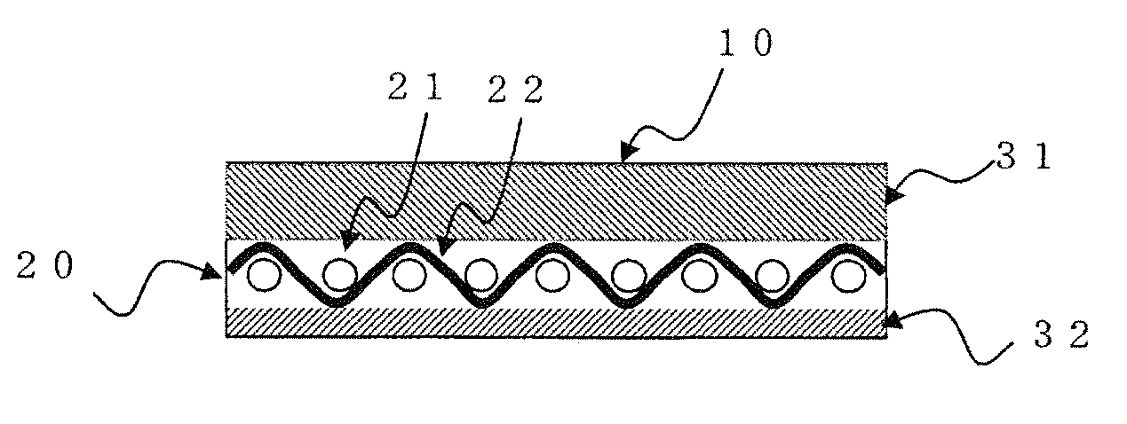
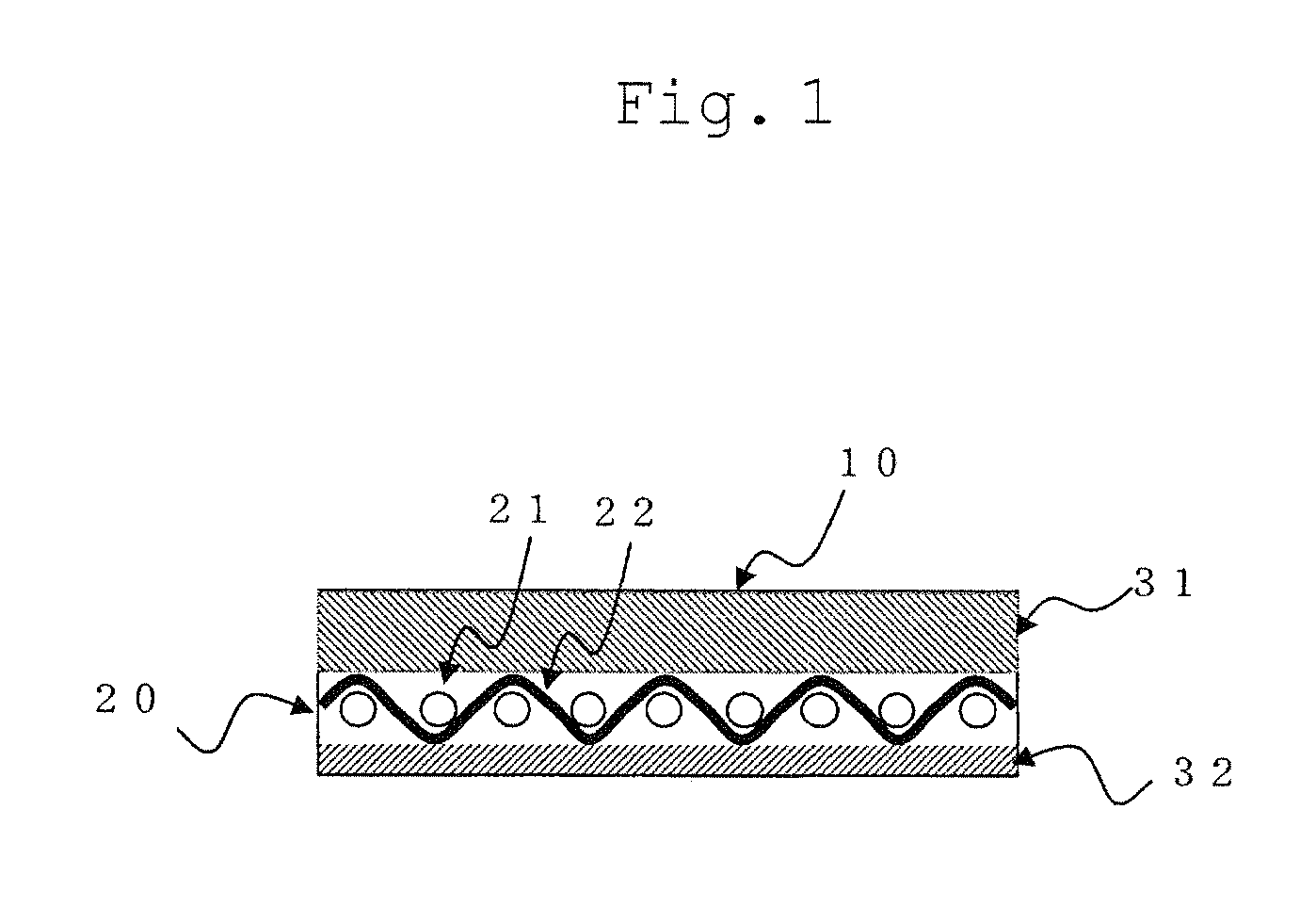
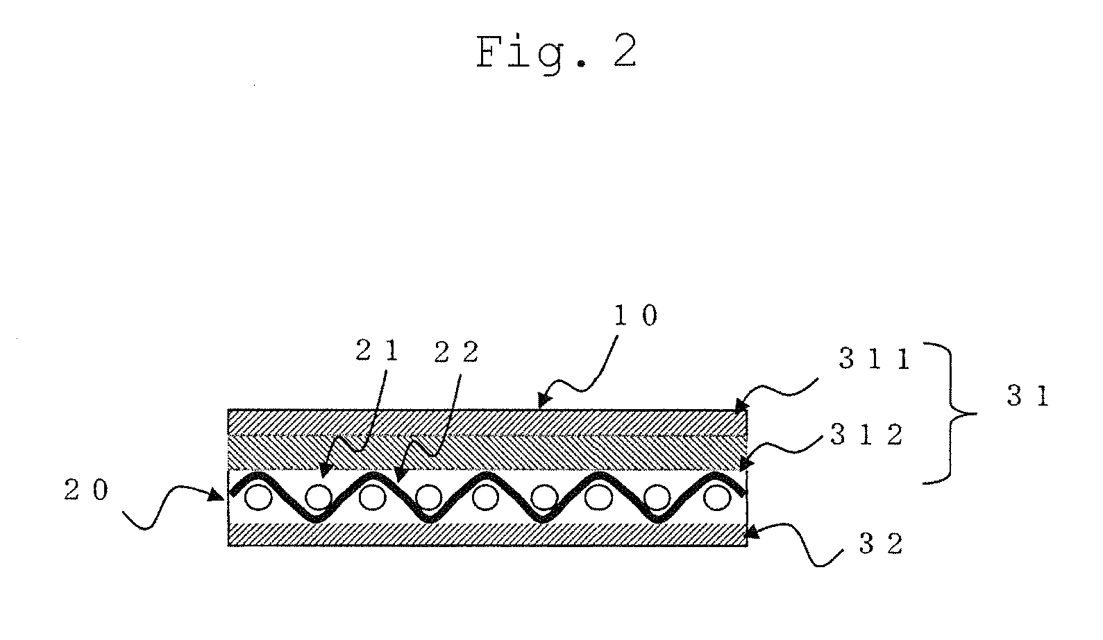
[0047]In order to test examples and comparative examples under the same condition, all the felts have common basic structure as follows:

Base body: 1 / 1 plain-weave fabric woven with nylon monofilament twist yarn, with a basis weight of 750 g / m2

The wet paper web side batt fiber layer: 17dtex nylon 6 staple fiber, with a basis weight of 500 g / m2

The backside batt fiber layer: a fiber layer of a blend of 17dtex staple fiber of the core-in-sheath conjugate fiber specified below and 17dtex staple fiber of nylon 6, with a total basis weight of 200 g / m2. The content of the core-in-sheath conjugate fiber is specified in Table 1.

Core-in-sheath conjugate fiber: a synthetic fiber, the core member being nylon 6 and the sheath member being copolymerized nylon 6 / 12, the weight percent ratio of which is 1:1.

[0048]The wet paper web side batt fiber layer and the backside batt fiber layer we...


PUM


Abstract

The papermaking felt 10 of the present invention comprises a base body 20, a wet paper web side batt fiber layer 31, and a backside batt fiber layer 32, in which the wet paper web side batt fiber layer 31 is contained in high molecular weight elastic material and the backside batt fiber layer 32 includes a melting fiber.

Description

TECHNICAL FIELD[0001]The present invention relates to a papermaking felt used in a papermaking machine (hereinafter also referred to as a “felt”).BACKGROUND ART[0002]A papermaking process in a papermaking machine consists of three main parts, namely, forming, press, and drying sections, through which a wet paper web is dewatered continually.[0003]Each section employs papermaking equipments with a dewatering function.[0004]Conventionally, a papermaking felt is employed in the press section, where a felt with a wet paper web thereon is pressurized by a pressing system so that water contained in the wet paper web moves into the felt.[0005]The press portion of the press section is generally composed of a pair of press rolls or a press roll coupled with a shoe shaped to conform to the peripheral surface of the press roll.[0006]Referring to FIG. 1, the structure of the felt is to be described. FIG. 1 illustrates a cross-sectional view of the felt in the cross (CMD) direction. A papermakin...

Claims


Application Information

Patent Timeline
Patent Type & Authority Applications(United States)
IPC IPC(8): D21G9/00
CPCD21F7/083
Inventor OHUCHI, TAKASHI
Owner ICHIKAWA ELECTRIC CO LTD
Why Eureka
Try Eureka