Skate-Wheel Positioning Structure

Inactive Publication Date: 2010-10-07
CHEN PO FENG
View PDF12 Cites 10 Cited by
  • Summary
  • Abstract
  • Description
  • Claims
  • Application Information

AI Technical Summary

Benefits of technology

[0007]A first object of the present invention is to provide a Skate-Wheel positioning structure having position-limiting protrusions that are fixedly attached to the axle by mechanical force or integrally formed with the axle. Therefore, there is no need to use manual labor to fit the spacers onto the axle. Consequently, assembly may be sped up, less manual labor is needed and the cost for the purchase of spacers may be eliminated.
[0008]A second object of the present invention is to provide a Skate-Wheel positioning structure that has the advantages of simple structu

Problems solved by technology

The conventional elongated cylindrical rollers are most widely used, but their manufacturing cost is higher because mor

Method used


Image

  • Skate-Wheel Positioning Structure
  • Skate-Wheel Positioning Structure
  • Skate-Wheel Positioning Structure

Examples


Example

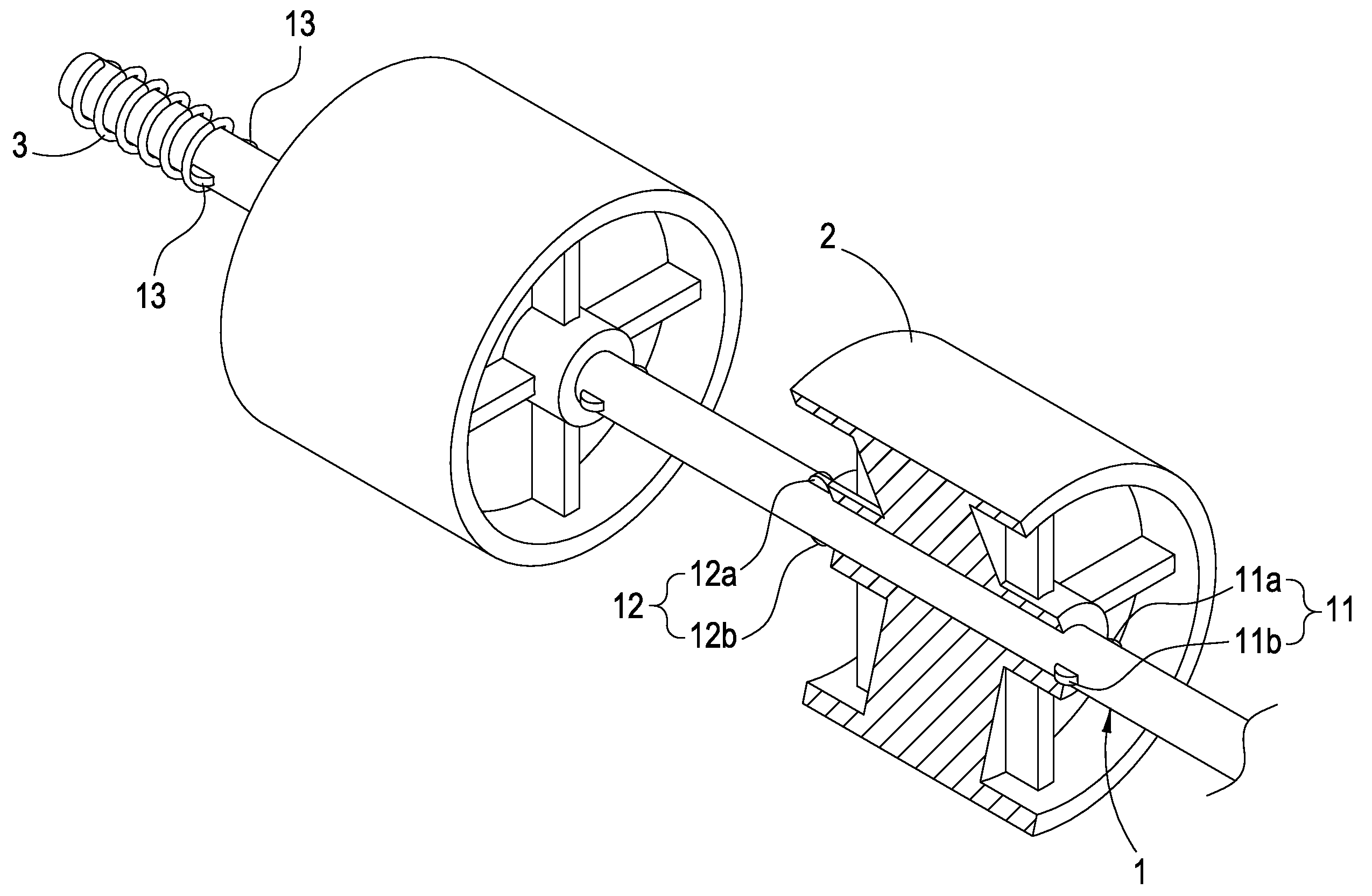
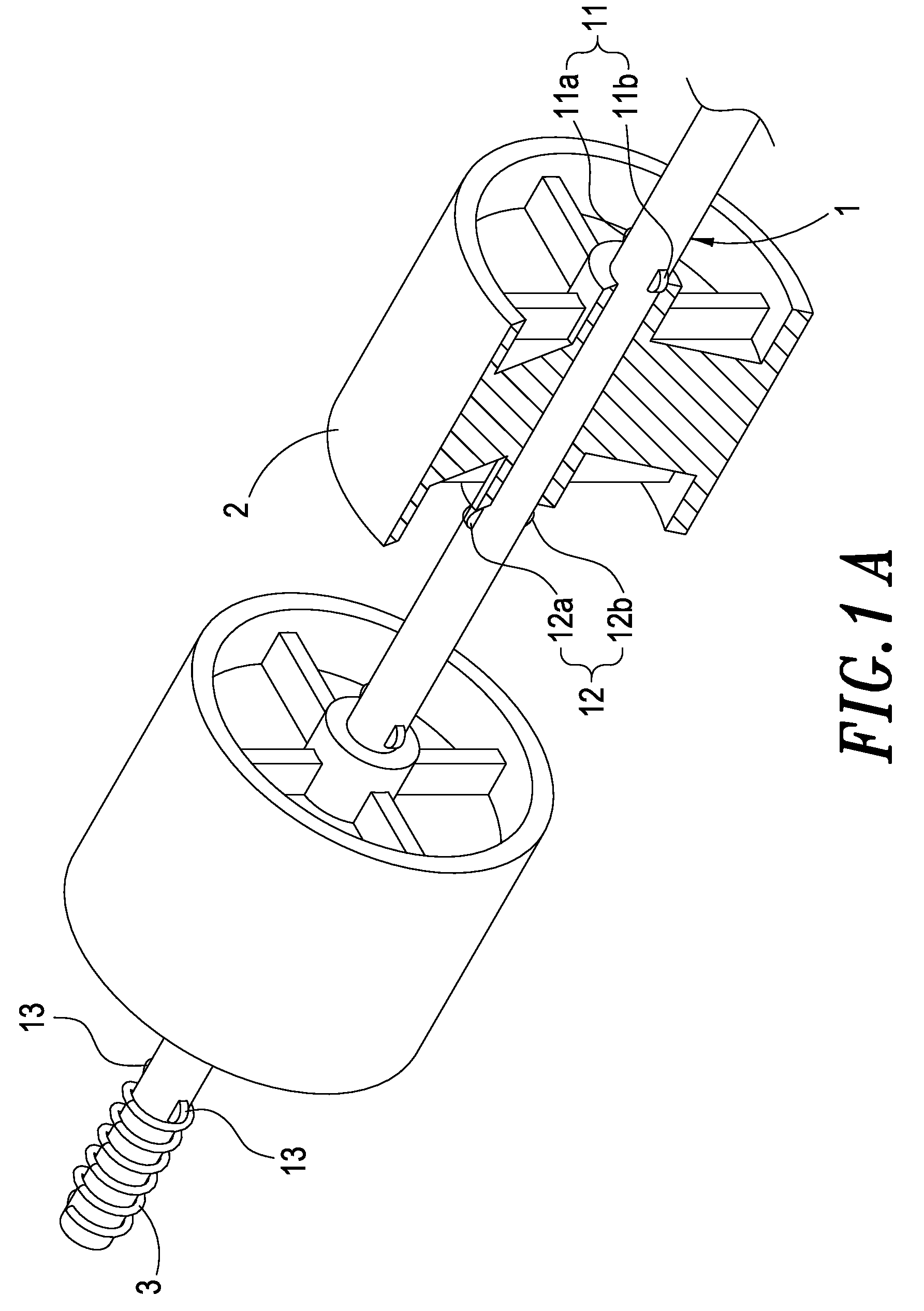
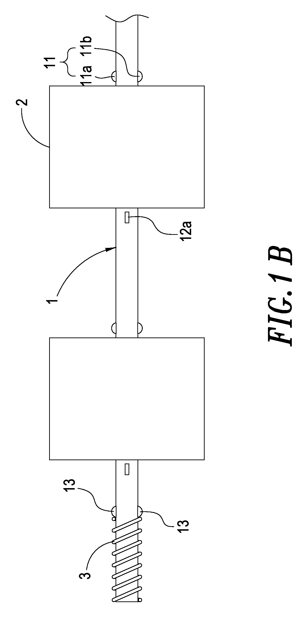
[0015]Please see FIGS. 1A, 1B, 2A, 2B and 3, which are drawings schematically illustrating the Skate-Wheel positioning structure of the present invention. The Skate-Wheel positioning structure of the present invention comprises an axle 1 and several protrusions 11 and 12.

[0016]A first set of position-limiting protrusions 11 is disposed on one side of the Skate-Wheel 2, and a second set of position-limiting protrusions 12 is disposed on the other side of the Skate-Wheel 2. The first set of position-limiting protrusions 11 includes at least two position-limiting protrusions 11a and 11b. The second set of position-limiting protrusions 12 includes at least two position-limiting protrusions 12a and 12b. A third set of position-limiting protrusions 13 is disposed on an appropriate location of the axle 1, and a spring 3 is fitted beside the third set of position-limiting protrusions 13, which can limit the position of the spring 3. At least two sets of the position-limiting protrusions 11 ...


PUM


Abstract

A Skate-Wheel positioning structure includes a plurality of Skate-Wheels disposed on an axle. A set of protrusions is disposed on either side of each Skate-Wheel to limit the position of the Skate-Wheel.

Description

BACKGROUND OF THE INVENTION[0001]1. Field of the Invention[0002]The invention generally relates to a Skate-Wheel positioning structure. More particularly, the invention relates to a Skate-Wheel positioning structure in which a set of position-limiting protrusions is disposed on either side of each Skate-Wheel to limit the position of each Skate-Wheel.[0003]2. Description of the Prior Art[0004]There are several types of rollers used for the conveyor system. The conventional elongated cylindrical rollers are most widely used, but their manufacturing cost is higher because more material is needed. Another type uses several Skate-Wheels to replace each elongated cylindrical rollers and spacers are used to limit the positions of these Skate-Wheels; therefore, less material is needed. However, because these spacers are fitted onto the axles by manual labor, labor cost is increased.[0005]From the above, we can see that the rollers of the prior art have many disadvantages and needs to be im...

Claims


Application Information

Patent Timeline
IPC IPC(8): A63C17/22B65G13/00
CPCB65G39/04
Inventor CHEN, PO-FENG
Owner CHEN PO FENG
Why Eureka
Try Eureka