Input device with capacitive force sensor and method for constructing the same

a capacitive force sensor and input device technology, applied in the field of input devices, can solve the problems of increasing the cost of the device, general unreliability of methods, inaccurate data,

Inactive Publication Date: 2010-10-07
SYNAPTICS INC
View PDF72 Cites 144 Cited by
  • Summary
  • Abstract
  • Description
  • Claims
  • Application Information

AI Technical Summary

Problems solved by technology

However, such methods are generally unreliable and inaccurate.
Other current force determining systems utilize technologies that are complete

Method used


Image

  • Input device with capacitive force sensor and method for constructing the same
  • Input device with capacitive force sensor and method for constructing the same
  • Input device with capacitive force sensor and method for constructing the same

Examples


Embodiment Construction

[0017]The following detailed description is merely exemplary in nature and is not intended to limit the invention or the application and uses of the invention. Furthermore, there is no intention to be bound by any expressed or implied theory presented in the preceding technical field, background, brief summary or the following detailed description.

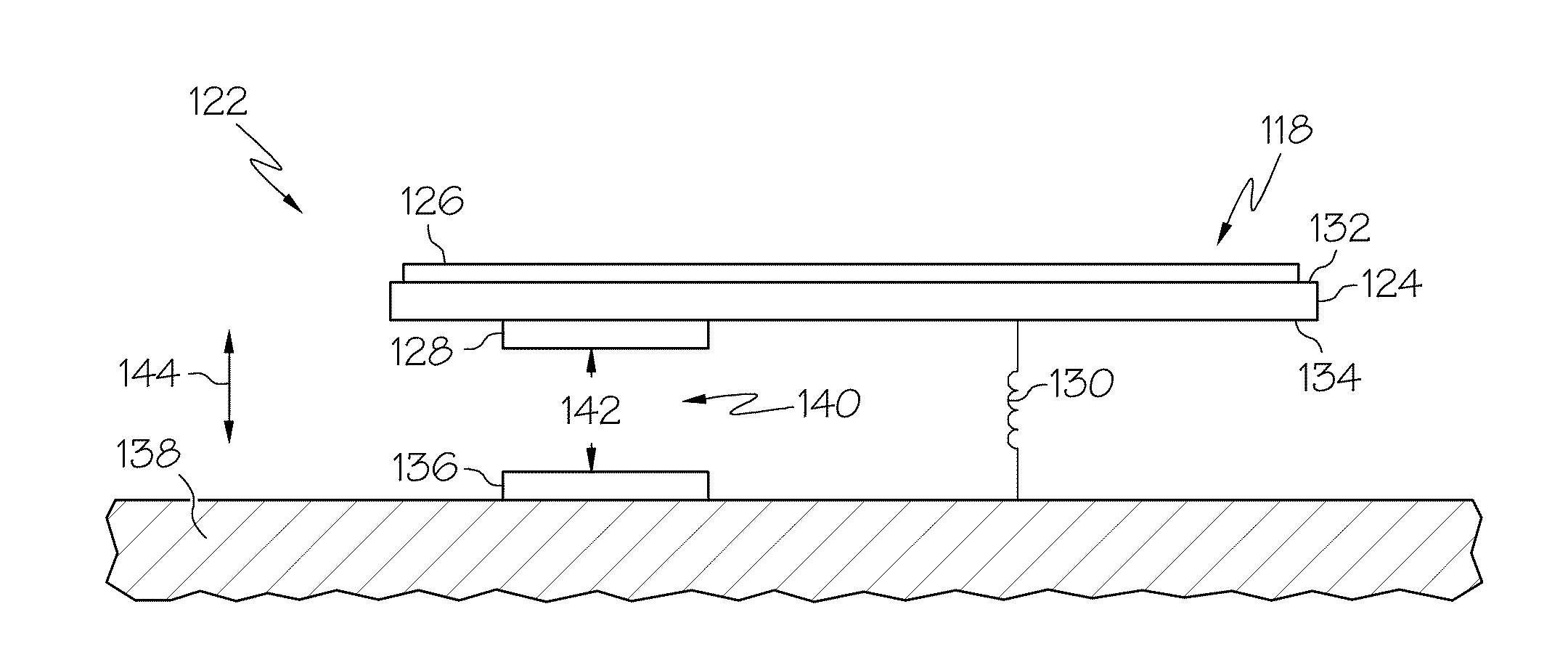
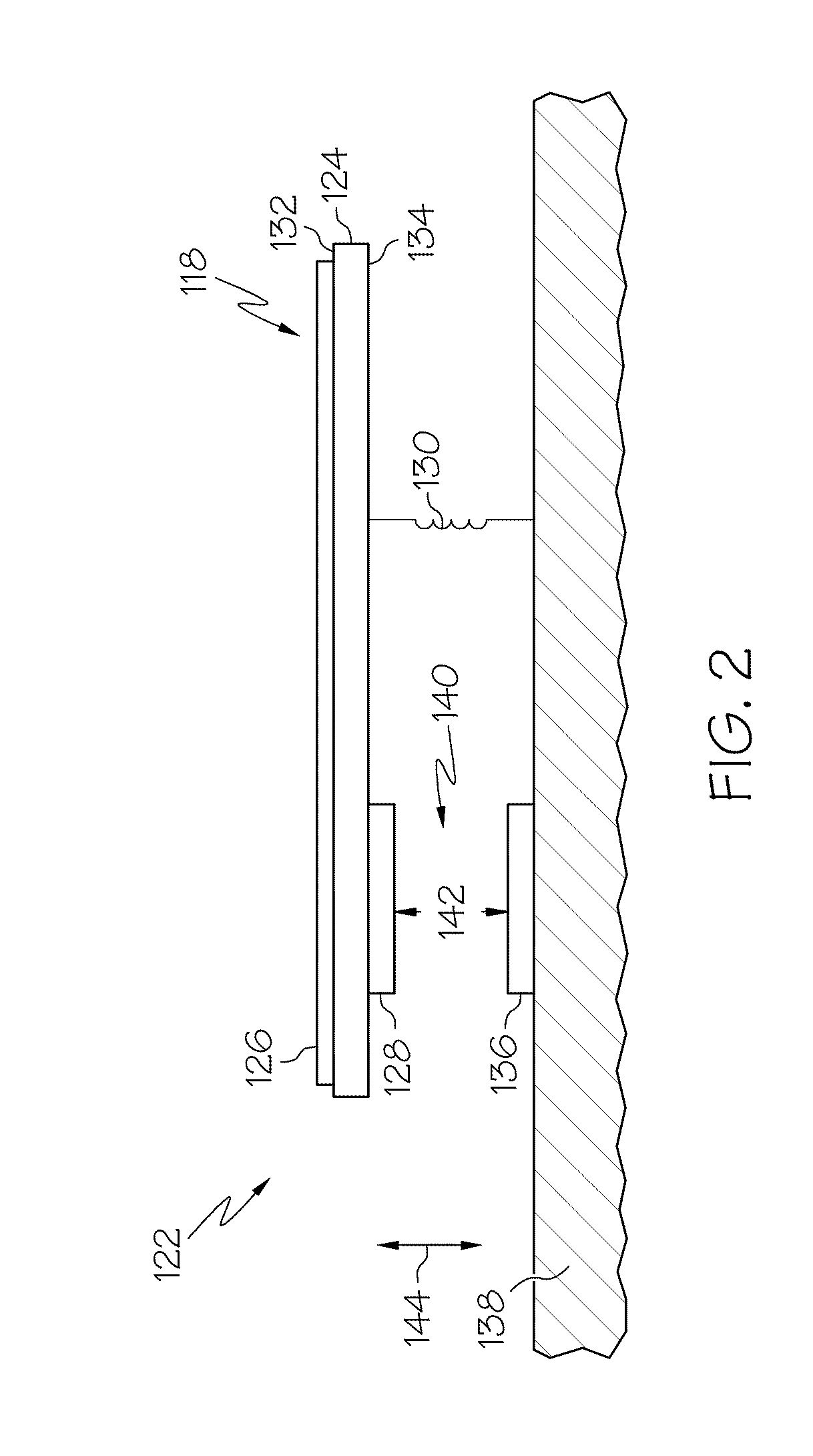
[0018]Various aspects of the present invention provide input devices and methods for using and constructing such input devices that facilitate improved usability. Specifically, the input devices and methods provide a simple and reliable arrangement for determining a force applied directly or indirectly onto the input devices by an input object onto sensing regions associated with the input devices.

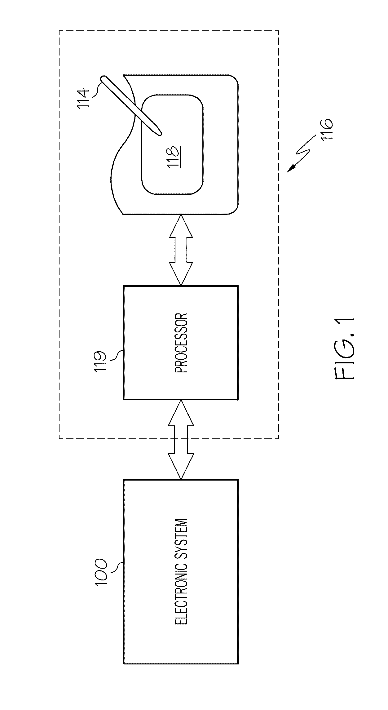
[0019]Turning now to the figures, FIG. 1 is a block diagram of an exemplary electronic system 100 that is coupled to an input device, or proximity sensor device, 116. The electronic system 100 is meant to represent any type of personal computer, ...


PUM


Abstract

Input devices which include a capacitive force sensor, along with methods of making and using such, are provided. The input device includes a structural component having first and second substantially opposing sides, a plurality of sensor electrodes located on the first side of the structural component, the plurality of sensor electrodes configured to capacitively sense positional information associated with user input in a sensing region, a first capacitive electrode located on the second side of the structural component, the first capacitive electrode being configured to capacitively couple to a second capacitive electrode that is separated from the first capacitive electrode by a gas and moveable relative to the first capacitive electrode, and a biasing member configured to be physically coupled to the structural component such that a force associated with the user input causes a change in a separation distance between the first and second capacitive electrodes based on the force.

Description

FIELD OF THE INVENTION[0001]This invention generally relates to electronic devices, and more specifically relates to input devices, such as proximity sensor devices.BACKGROUND OF THE INVENTION[0002]Proximity sensor devices (also commonly called touchpads or touch sensor devices) are widely used in a variety of electronic systems. A proximity sensor device typically includes a sensing region, often demarked by a surface, which uses capacitive, resistive, inductive, optical, acoustic and / or other technology to determine the presence, location and / or motion of one or more fingers, styli, and / or other objects. The proximity sensor device, together with finger(s) and / or other object(s), may be used to provide an input to the electronic system. For example, proximity sensor devices are used as input devices for larger computing systems, such as those found integral within notebook computers or peripheral to desktop computers. Proximity sensor devices are also used in smaller systems, incl...

Claims


Application Information

Patent Timeline
IPC IPC(8): G06F3/045
CPCG06F3/044G06F3/0414G06F3/0418G06F3/0447G06F2203/04105
Inventor BOLENDER, ROBERT J.
Owner SYNAPTICS INC
Why Eureka
Try Eureka