
Backlight unit and liquid crystal display using the same

a backlight unit and liquid crystal display technology, applied in static indicating devices, lighting and heating apparatuses, instruments, etc., can solve the problems of difficult to improve static contrast, and complicated local dimming methods, so as to achieve the effect of improving contrast properties

Active Publication Date: 2010-10-07
LG DISPLAY CO LTD
View PDF5 Cites 37 Cited by
  • Summary
  • Abstract
  • Description
  • Claims
  • Application Information

AI Technical Summary

Benefits of technology

[0010]Exemplary embodiments of the invention provide a backlight unit capable of improving contrast properties by implementing a local dimming method while making the backlight unit slim, and a liquid crystal display using the same.

Problems solved by technology

The method improving the picture quality by modulating light-incedent from the backlight unit has a limitation.
The global dimming method may improve dynamic contrast measured between a previous frame and a next frame but it is difficult to improve static contrast.
However, the local dimming method needs a very complicated construction and algorithm because it makes luminance differences and flickers between a plurality of blocks divided in the display screen and flicker and also it needs many circuit elements.
However, it is impossible to apply the local dimming method to of the edge type backlight unit because the light source illustrates one side of the light guide plate and the light guide plate serves to convert a spot light source or a line light source into a surface light source.
Even though the direct type backlight unit implements the local dimming method because the plurality of light sources are disposed under the diffusion plate and can be independently controlled, it is difficult to reduce a thickness thereof.
Accordingly, it causes a problem to make a slim design of the liquid crystal display difficult.
However, the above methods also may cause an increased cost and have definite limitations in respect of improving the diffusion of light.

Method used


Image

  • Backlight unit and liquid crystal display using the same
  • Backlight unit and liquid crystal display using the same
  • Backlight unit and liquid crystal display using the same

Examples


Embodiment Construction

[0033]Hereinafter, exemplary embodiments of the invention will be described in detail with reference to the accompanying drawings so that this disclosure is thorough and complete and fully conveys the concept of the invention to those skilled in the art. This invention may, however, be embodied in many different forms and should not be construed as being limited to the embodiments set forth herein.

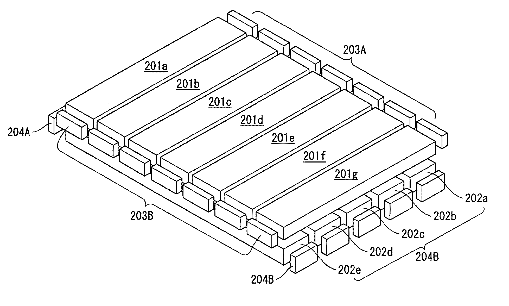
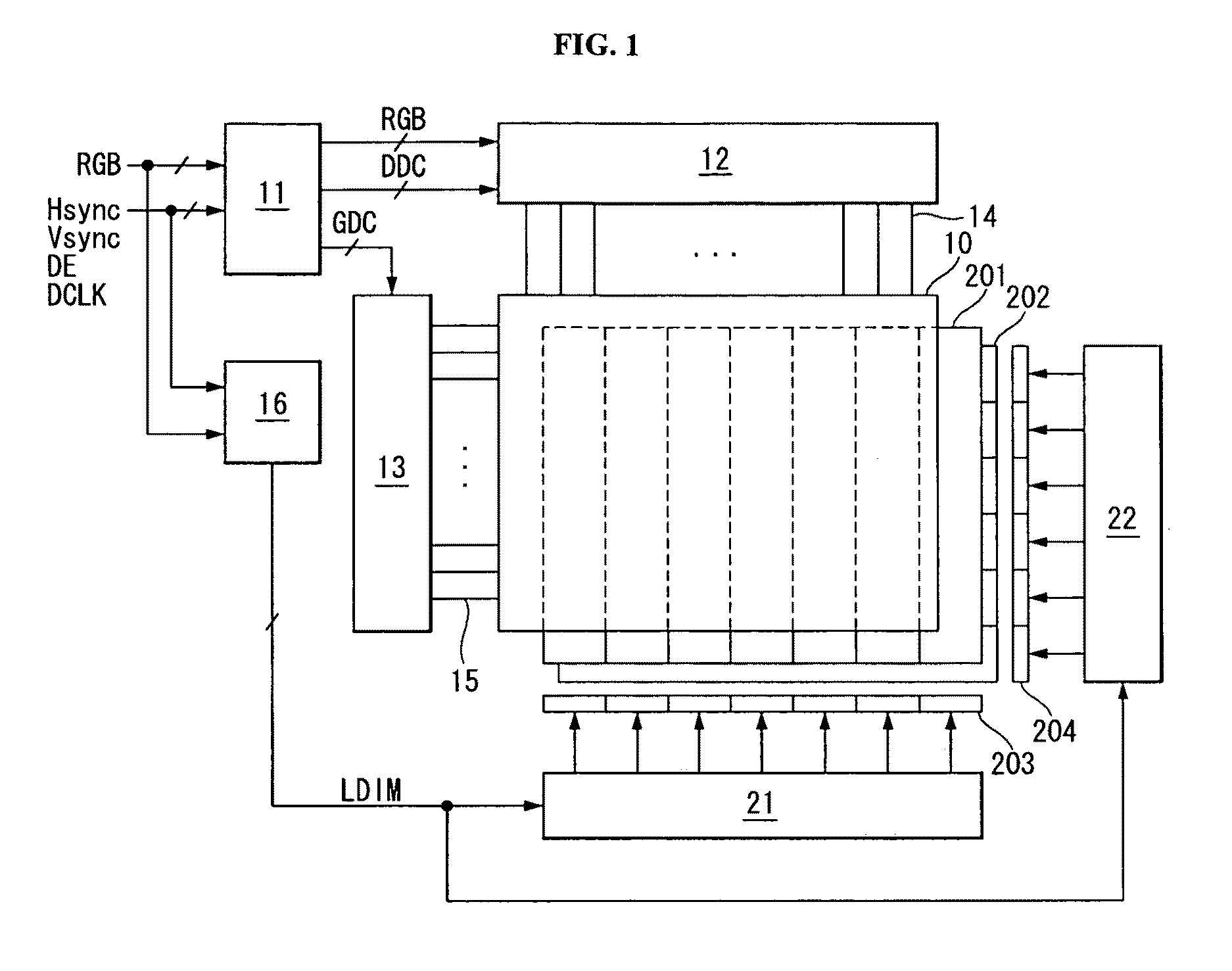
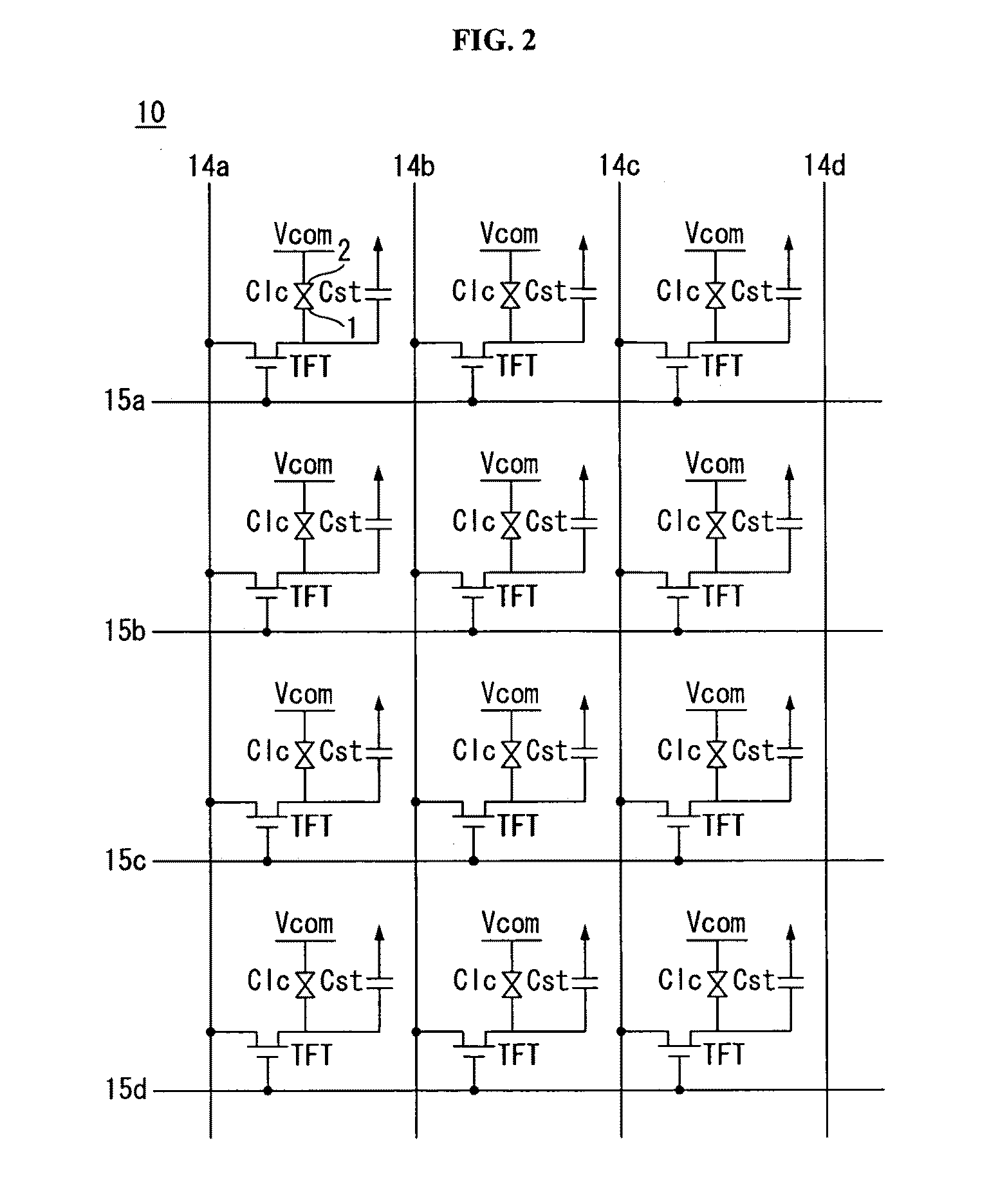
[0034]Referring to FIGS. 1 to 3, a liquid crystal display according to an exemplary embodiment of the invention comprises a liquid crystal display panel 10, a data driving part 12 for driving data lines 14 of the liquid crystal display panel 10, a gate driving part 13 for driving gate lines 15 of the liquid crystal display panel 10, a timing controller 11 for controlling the data driving part 12 and the gate driving part 13, a backlight unit for illuminating light to the liquid crystal display panel 10, light array driving parts 21 and 22 for driving light sources 203 and 204 of the backli...


PUM

PropertyMeasurementUnit
frequencyaaaaaaaaaa
luminous fluxaaaaaaaaaa

Abstract

A backlight unit capable of improving contrast properties by implementing a local dimming method while making the backlight unit slim, and a liquid crystal display using the same are provided. The backlight unit includes a first light guide plate array including a plurality of first light guide plates arranged in parallel in a first direction to define a first light guide channels; a second light guide plate array including a plurality of second light guide plates arranged in parallel in a second direction intersected with the first direction to a second light guide channels; a first light array arranged near at least one end of the first light guide plate array to illuminate light to the at least one end of the first light guide plate array; and a second light array arranged near at least one end of the second light guide plate array to illuminate light to the at least one end of the second light guide plate array.

Description

[0001]This application claims the benefit of Korea Patent Application No. 10-2009-0028154 filed on Apr. 1, 2009, which is incorporated herein by reference for all purposes as if fully set forth herein.BACKGROUND OF THE INVENTION[0002]1. Field of the Invention[0003]Exemplary embodiments of the invention relate to a backlight unit capable of local dimming and a liquid crystal display using the same.[0004]2. Discussion of the Related Art[0005]A liquid crystal display according to an active matrix driving method displays moving pictures using thin film transistors (TFTs) as switching elements. The liquid crystal display is applied television sets as well as portable information devices, office automation apparatuses, computers because it is possible to be made thinner than a cathode ray tube (CRT). Accordingly, the liquid crystal display rapidly replaces the CRT in a recent.[0006]The liquid crystal displays have an increasing application range because of light-weight, thin, low-power co...

Claims


Application Information

Patent Timeline
Patent Type & Authority Applications(United States)
IPC IPC(8): G02F1/13357F21V8/00
CPCG02F1/133615G09G3/3426G09G2320/0646G02F1/1335
Inventor HAN, JAEJUNGBANG, JUYOUNGJUN, DUKJIN
Owner LG DISPLAY CO LTD
Learn More