
Light modulation element positioning method for projector, and projector

Active Publication Date: 2010-10-07
SEIKO EPSON CORP
View PDF14 Cites 5 Cited by
  • Summary
  • Abstract
  • Description
  • Claims
  • Application Information

AI Technical Summary

Benefits of technology

[0009]It is an advantage of some aspects of the invention to provide a light modulation element positioning method for a projector, and a projector, which can easily and highly accurately position light modulation elements such that respective image lights supplied from two light modulation element units can be set in a desired pixel shift condition.
[0012]When the first light modulation element unit and the second light modulation element unit are positioned in advance such that the respective light modulation elements are in the ideal pixel shift condition, the first image light supplied from the first light modulation element unit and the second image light supplied from the second light modulation element unit can be displayed in the ideal pixel shift condition only by appropriately positioning the first light modulation element unit and the second light modulation element unit. In this case, the first light modulation element unit and the second light modulation element unit are positioned such that the color of the combined light produced by combining the first image light and the second image light using a polarized light combining system becomes the predetermined color. Thus, positioning can be easily and highly accurately performed by referring to a positioning target thus established.
[0014]According to this method, positioning the pixels of the first through third images and positioning the pixels of the fourth through sixth images are performed in advance before the first light modulation element unit and the second light modulation element unit are assembled into the projector. Thus, assembly of the projector can be facilitated. In this case, positioning the pixels of the first through third images and positioning the pixels of the fourth through sixth images are executed by using a dedicated positioning device. The dedicated light modulation element positioning device can use a projection lens and other optical systems having higher performance than that of a projector available on the market. Thus, positioning can be performed highly accurately and relatively easily.
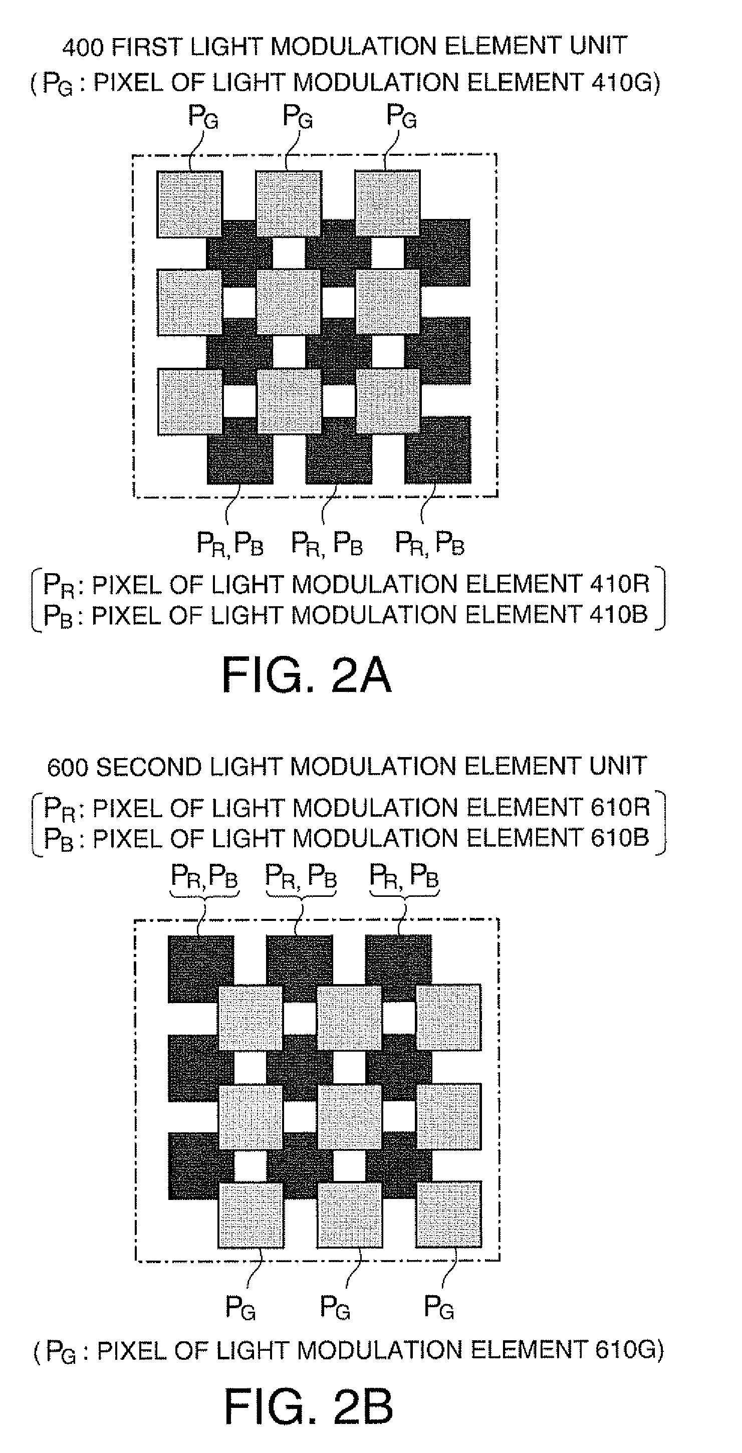
[0018]According to this method, the first light modulation element unit and the second light modulation element unit are positioned such that the color of the combined light supplied from the combining system becomes white (W). In this case, the target for positioning the first light modulation element unit and the second light modulation element unit can be clarified, and thus positioning can be easily and highly accurately performed. When the light modulation element corresponding to the one color light (green light) of the first light modulation element unit is actuated, green light is supplied from the first light modulation element unit. When the two light modulation elements corresponding to the two color lights (red light and blue light) of the second light modulation element unit are actuated, red light and blue light are supplied from the second light modulation element unit. Thus, the combined light supplied from the combining system becomes white (W). This applies when the two light modulation elements corresponding to the two color lights (red light and blue light) of the first light modulation element unit and the one light modulation element corresponding to the color light (green light) of the second light modulation element unit are actuated.
[0020]According to the projector of the second aspect, images are projected in an ideal pixel shift condition. Thus, image display with high resolution can be achieved. Moreover, the first light modulation element unit and the second light modulation element unit are easily and highly accurately positioned. Thus, even when the positional relationship between the first light modulation element unit and the second light modulation element unit deviates from the ideal relationship by change with elapse of time, the positions can be easily re-adjusted.

Problems solved by technology

Particularly in case of the pixel shift projection, a reference and a target for positioning are difficult to be determined in setting a desired pixel shift condition.
Thus, the control required for the pixel shift projection becomes more difficult.
As explained above, in case of the pixel shift projection, a reference and a target for positioning are difficult to be determined in setting the desired pixel shift condition.
Thus, the positioning becomes further difficult, and the productivity of the projector lowers.

Method used


Image

  • Light modulation element positioning method for projector, and projector
  • Light modulation element positioning method for projector, and projector
  • Light modulation element positioning method for projector, and projector

Examples


Embodiment Construction

[0026]An exemplary embodiment according to the invention is hereinafter described.

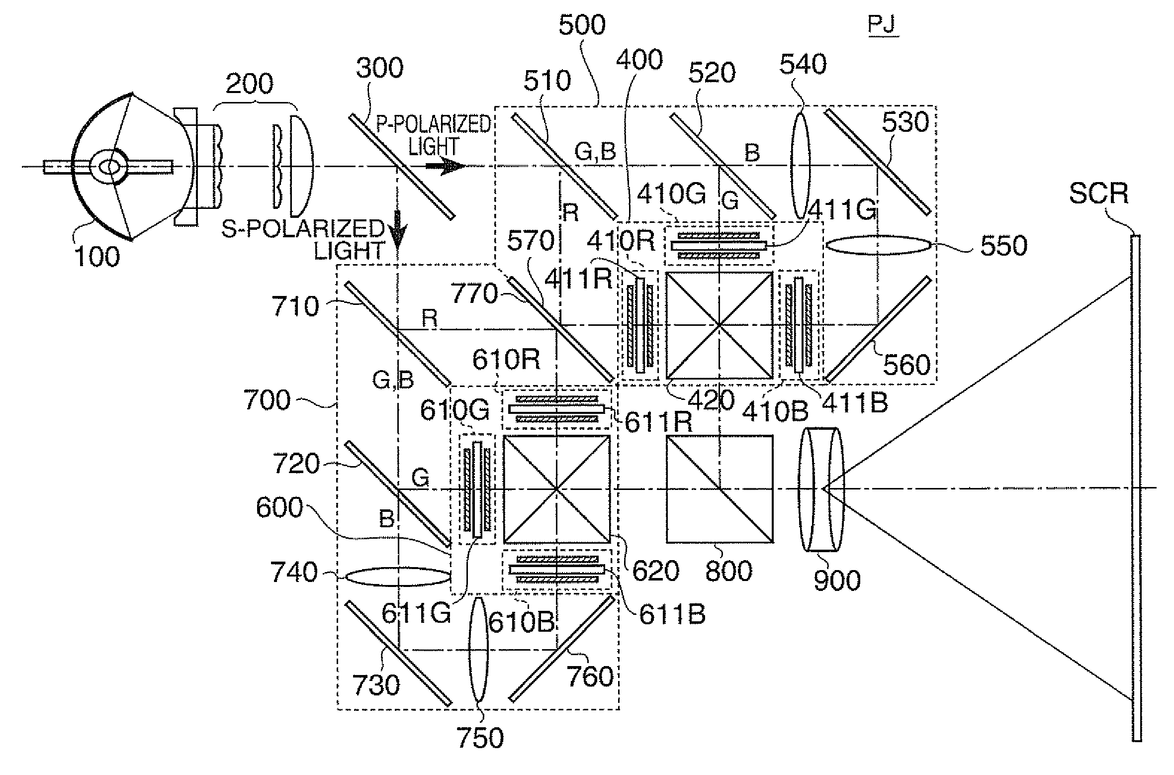
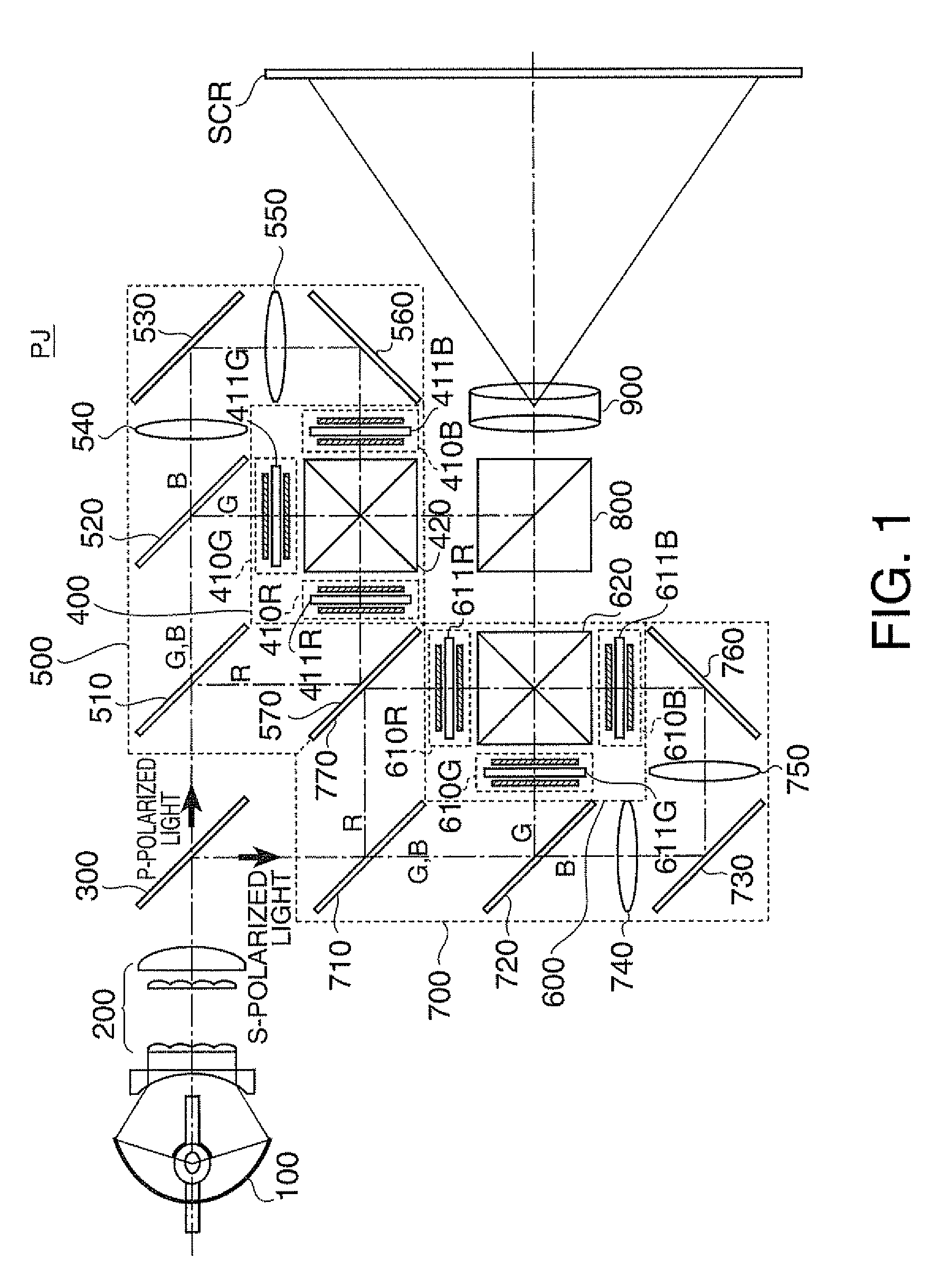
[0027]FIG. 1 illustrates the structure of optical systems included in a projector PJ according to this embodiment. As illustrated in FIG. 1, the projector PJ in this embodiment includes a light source 100 which emits lights containing a first color light (red light), a second color light (green light), and a third color light (blue light), an integrator system 200, a polarized light separation mirror 300 as a polarized light separation system, a first light modulation element unit 400 which supplies first image light, a first light guide system 500 which guides a first polarized light component (p-polarized light) separated by the polarized light separation mirror 300 to the first light modulation element unit 400, a second light modulation element unit 600 which supplies second image light, a second light guide system 700 which guides a second polarized light component (s-polarized light) separated by...


PUM


Abstract

A method for positioning a light modulation element of a projector comprising: providing the projector including a first light modulation element unit having a first through a three light modulation elements, a second light modulation element unit having a fourth through a sixth light modulation elements, and a combining system for combining first image light supplied from the first light modulation element unit and second image light supplied from the second light modulation element unit and supplying combined light, positioning first light modulation element unit and second light modulation element unit such that color of combined light of color lights obtained from the first light modulation element, the second light modulation element, and the sixth light modulation element and combined by the combining system becomes a predetermined color.

Description

BACKGROUND[0001]1. Technical Field[0002]The present invention relates to a light modulation element positioning method for a projector, and a projector.[0003]2. Related Art[0004]Currently, such a projection method is known which positions two projectors such that pixels of a light modulation element included in one of the two projectors agree with corresponding pixels of a light modulation element included in the other projector. By this method, identical images can be projected from the projectors onto the same screen (this method is called “stack projection”). Image light projected by the stack projection has approximately twice higher luminance, and becomes considerably bright image light when projected on the screen. Also, such a projection method has been practiced which shifts the pixels of the light modulation element of the one projector from the corresponding pixels of the light modulation element of the other projector by ½ pixel for each in an oblique direction and projec...

Claims


Application Information

Patent Timeline
IPC IPC(8): G03B21/14
CPCG03B21/14G03B35/12H04N9/3197H04N9/317H04N9/3105G03B21/006G03B21/142
Inventor NAGAI, KAZUKI
Owner SEIKO EPSON CORP
Learn More