Method for controlling uplink power control considering multiplexing rate/ratio

a technology of power control and multiplexing rate, applied in the field of transmission power control, can solve the problems of increasing system interference, reducing the reception performance of bs, and affecting the performance of mss which uses the same resource in a neighboring cell adjacent to the specific cell, so as to reduce the level of system interference

Active Publication Date: 2010-10-07
LG ELECTRONICS INC
View PDF14 Cites 110 Cited by
  • Summary
  • Abstract
  • Description
  • Claims
  • Application Information

AI Technical Summary

Benefits of technology

[0023]According to the present invention, it is possible to reduce the level of system interference when two or more mobile s

Problems solved by technology

First, each MS needs only one power amplifier since only one transmission path is necessary for the MS.
However, in a wireless mobile communication system, as the number of users increases, the sum of powers of signals transmitted from users increases and thus the interference between communication devices in the sy

Method used


Image

  • Method for controlling uplink power control considering multiplexing rate/ratio
  • Method for controlling uplink power control considering multiplexing rate/ratio
  • Method for controlling uplink power control considering multiplexing rate/ratio

Examples


embodiment 1

Open-Loop Power Control

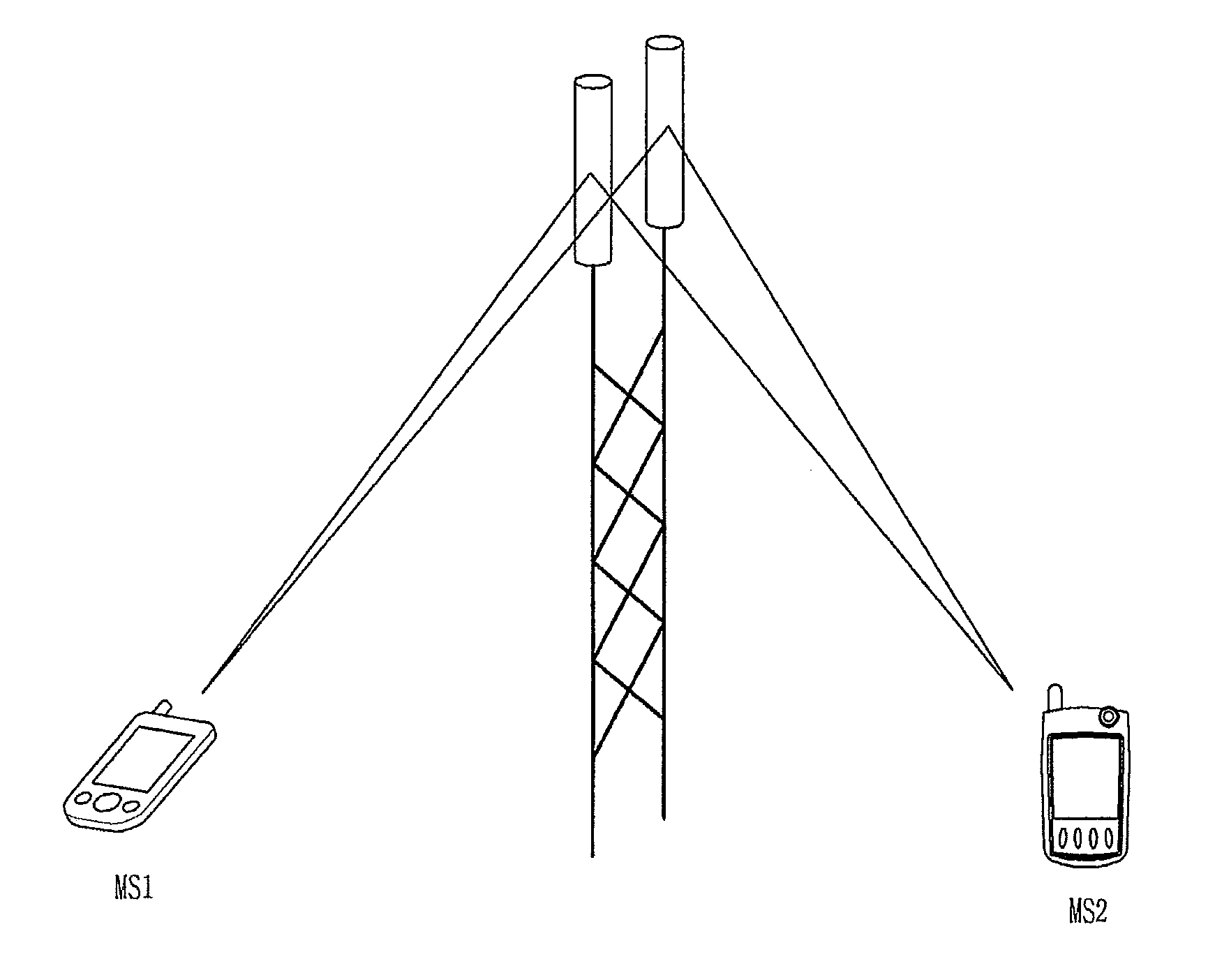
[0108]Reference will now be made to how uplink open-loop power control is performed according to an embodiment of the present invention in the case where one MS uses one time-frequency-domain resource and in the case where two or more MSs simultaneously use one time-frequency-domain resource.

[0109]The method for controlling power when two or more MSs use the same resource according to this embodiment uses a power control scheme represented by a function of the number of simultaneous users M. Basically, this method does not reduce performance while maintaining a level of interference that can be obtained through the power control method in the case where one MS uses one time-frequency-domain resource.

[0110]For example, let us consider a first scheme in which a signal transmitted from one antenna of one MS through one (time or frequency) resource region is received through a plurality of antennas of a BS and a second scheme in which two or more MSs simultaneousl...

embodiment 2

Closed-Loop Power Control 1

[0121]Closed-loop power control according to another embodiment of the present invention can be represented by Mathematical Expression 6 or Mathematical Expression 7.

Pnew=Plast+ΔTPC  [MATHEMATICAL EXPRESSION 6]

Pnew=A+ΔTPC  [MATHEMATICAL EXPRESSION 7]

[0122]In Mathematical Expression 6, Pnew represents transmission power in a new frame, Plast represents transmission power in a previous frame, and ΔTPC represents the difference between the two transmission powers. In Mathematical Expression 7, “A” represents a reference transmission power, which may be equal to that of the equation of closed-loop power control for one MS. The BS can transmit “ΔTPC” to the MS at regular or irregular intervals. When the value “ΔTPC” is transmitted at regular intervals, the period at intervals of which the value is changed may be, without being limited to, a subframe(s), a frame(s), or a radio frame(s).

[0123]FIG. 14 illustrates a relationship between reception of a transmission ...

embodiment 3

[0140]Power control according to another embodiment of the present invention can be represented by Mathematical Expressions 8 to 11.

CLPCnew(dBm)=CLPClast(dBm)+g(M)(dB)  [MATHEMATICAL EXPRESSION 8]

CLPCnew(dBm)=CLPClast(dBm)+g(ΔM)(dB)  [MATHEMATICAL EXPRESSION 9]

CLPCnew(dBm)=CLPCreference(dBm)+h(M)(dB)  [MATHEMATICAL EXPRESSION 10]

CLPCnew(dBm)=CLPCreference(dBm)+h(ΔM)(dB)  [MATHEMATICAL EXPRESSION 11]

[0141]In Mathematical Expression 8, CLPCnew represents a transmission power of the current frame, CLPClast represents a transmission power of an immediately previous frame, and g(M) represents the difference between the two transmission powers. In the above embodiment associated with Mathematical Expression 6, the ΔTPC value, which is the difference between the transmission powers of the two signals, is transmitted. However, in the embodiment associated with Mathematical Expression 8, if the multiplexing ratio M is transmitted, then g(M) which is the difference between the transmission po...


PUM


Abstract

A method for maintaining system interference at a low level when two or more users use one resource region in a wireless mobile communication system is provided. To control an uplink transmission power in a broadband wireless mobile communication system in multi-cell environments, information regarding the number of users who share an uplink time-frequency resource region is received from a base station, a power adjustment value is calculated based on the received number of users, and the uplink transmission power is determined by reflecting the calculated power adjustment value in a reference transmission power. Here, when only one mobile station uses the uplink time-frequency resource region, the reference transmission power is equal to a transmission power of the mobile station.

Description

TECHNICAL FIELD[0001]The present invention relates to a broadband wireless mobile communication system, and more particularly, to transmission power control.BACKGROUND ART[0002]In order to increase data transfer rate and system capacity, next-generation mobile communication and wireless transmission systems use a Multi-Input Multi-Output (MIMO) scheme in which data is transmitted using multiple antennas.[0003]Single-user MIMO forms a channel matrix H between one Mobile Station (MS) having two or more antennas and a Base Station (BS) having two or more antennas. On the other hand, multi-user or collaborative MIMO forms a channel matrix H between two or more MSs, each having one antenna, and one BS having multiple antennas. The concept of uplink collaborative MIMO is illustrated in FIG. 1. This method has several advantages. First, each MS needs only one power amplifier since only one transmission path is necessary for the MS. In addition, even though each MS operates with other MSs i...

Claims


Application Information

Patent Timeline
IPC IPC(8): G08C17/00H04B7/00H04J1/00
CPCH04L1/0003H04L1/0009H04L1/0015H04W52/343H04W52/346Y02B60/50H04W52/146H04B7/2621Y02D30/70
Inventor KIM, DONG CHEOLIHM, BIN CHULKWAK, JIN SAMLEE, WOOK BONG
Owner LG ELECTRONICS INC
Why Eureka
Try Eureka