Communication route controller, radio communication device, communication route controlling method and communication method for radio communication device

a communication route and controller technology, applied in the field of communication route controllers, radio communication devices, communication route controlling methods and communication methods for radio communication devices, can solve the problems of radio communication devices, inability to respond to a and degradation of communication quality, and achieve the effect of sharp degradation of communication quality

Inactive Publication Date: 2010-10-07
KYOCERA CORP
View PDF13 Cites 11 Cited by
  • Summary
  • Abstract
  • Description
  • Claims
  • Application Information

AI Technical Summary

Benefits of technology

[0019]According to the aspects of the present invention, it is possible to provide a communication route controller, a radio communication device, a communication route controlling method and a communication method for a radio communication device, which are capable of, in the case of transmitting voice IP packets via a radio IP network, appropriately switching to a communication route via a different radio IP network while responding to a sharp degradation of the communication quality.

Problems solved by technology

However, the above communication route switching method has the following problem.
Specifically, since an average interval of transmitting RTCP packets is long (about two seconds), there may occur a case where the radio IP network constructed of a radio base station and the like cannot respond to a sharp degradation of the communication quality such as fading.
On the other hand, as for a degradation of the communication quality in an uplink of the radio IP network, there has been a problem that a communication controller, which is a receiving side, cannot determine whether or not to switch to a communication route via another radio IP network, because it is difficult for the communication controller to recognize the radio state of the radio IP network and the degradation of the communication quality.
Moreover, a radio communication device after transmission also has a similar problem because it is difficult for the radio communication device to recognize the degradation of the communication quality on the receiving side.

Method used


Image

  • Communication route controller, radio communication device, communication route controlling method and communication method for radio communication device
  • Communication route controller, radio communication device, communication route controlling method and communication method for radio communication device
  • Communication route controller, radio communication device, communication route controlling method and communication method for radio communication device

Examples


Embodiment Construction

[0027]Hereinafter, an embodiment of the present invention will be described. Note that similar or same reference numerals are given to similar or same elements in the following description of the drawings. In addition, it should be noted that the drawings are only schematic ones, and that a ratio of the dimensions is different from an actual one.

[0028]Thus, the specific dimensions must be determined in consideration of the following description. Moreover, obviously, the drawings include part in which a relation or ratio of the dimensions is different among the drawings.

(Entire Schematic Configuration of Communication System)

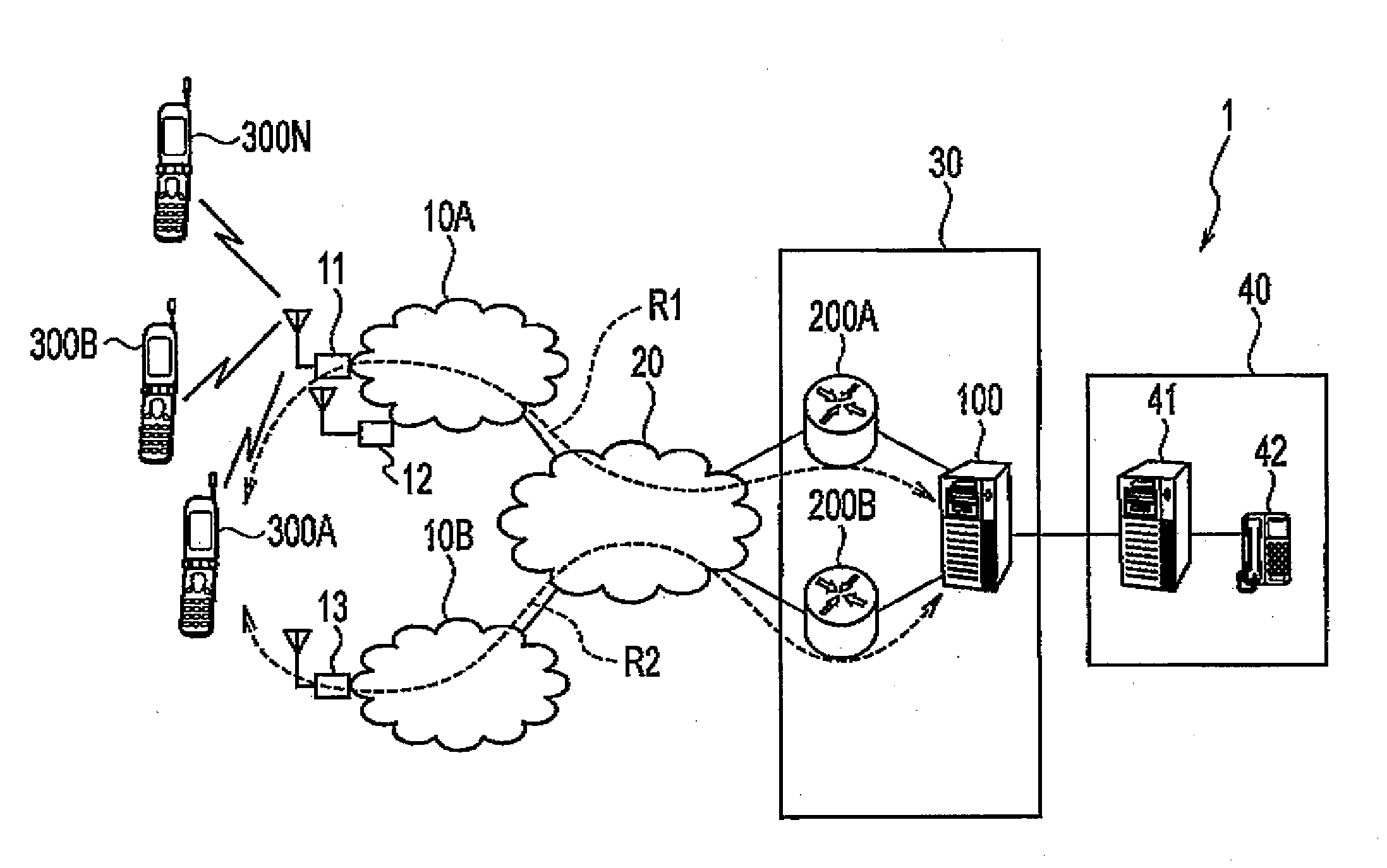
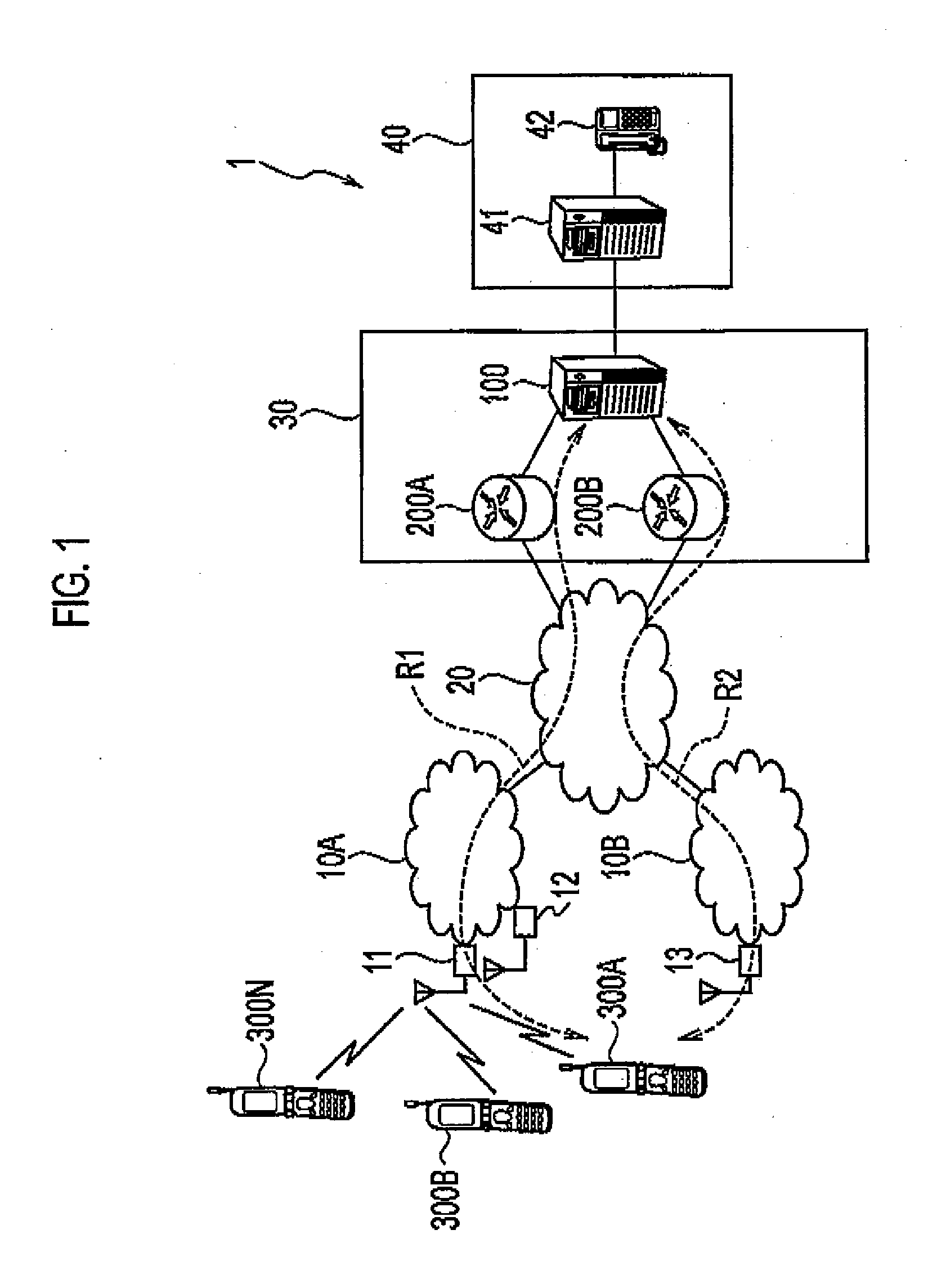
[0029]FIG. 1 is an entire schematic configuration diagram of a communication system 1 according to this embodiment. As shown in FIG. 1, the communication system 1 includes a radio IP network 10A and a radio IP network 10B. The radio IP network 10A is an IP network that allows IP packets to be transmitted.

[0030]The radio IP network 10A includes radio base stations...


PUM


Abstract

A switching server 100 relays VoIP packets transmitted from a cellular phone terminal 300A to an IP phone terminal 42, and sequentially acquires the receiving times of the VoIP packets received from the cellular phone terminal 300A. In addition, the switching server 100 switches a communication route R1 via a radio IP network 10A to a communication route R2 via a radio IP network 10B, on the basis of the multiple receiving times thus acquired.

Description

TECHNICAL FIELD[0001]The present invention relates to a communication route controller and a communication route controlling method for controlling a communication route to a radio communication device connect able to multiple radio IP networks, and relates to a radio communication device connectable to multiple radio IP networks, and a communication method for the radio communication device.BACKGROUND ART[0002]In recent years, a wide spread of IP networks supporting Internet Protocol (IP) has been remarkable. With the wide spread of IP networks, it has been becoming common to convert a voice signal into IP packets (hereinafter, referred to as voice IP packets) by use of a so-called VoIP technology and then to transmit the voice IP packets through an IP network.[0003]For the case of transmitting voice IP packets through the IP networks as described above, there has been disclosed a method for switching communication routes between telephone terminals on the basis of communication qu...

Claims


Application Information

Patent Timeline
Patent Type & Authority Applications(United States)
IPC IPC(8): H04W40/00H04L12/66H04L45/851H04M3/00H04W4/00H04W8/26H04W36/14H04W36/22H04W36/26H04W36/30H04W36/38H04W40/02H04W40/34H04W80/04H04W80/10H04W84/12H04W88/06H04W88/14
CPCH04W40/34H04M7/006H04L45/00
Inventor KITAJI, MITSUHIROYOKOTA, TOMOYOSHI
Owner KYOCERA CORP
Why Eureka
Try Eureka