High frequency ultrasonic convex array transducers and tissue imaging

a transducer and convex array technology, applied in the field of ultrasonic transducers and imaging systems, can solve the problems of low frame rate, still needing and may have to be translated mechanically

Inactive Publication Date: 2010-10-07
UNIV OF SOUTHERN CALIFORNIA
View PDF15 Cites 63 Cited by
  • Summary
  • Abstract
  • Description
  • Claims
  • Application Information

AI Technical Summary

Benefits of technology

[0017]The imaging system may be configured to use the Doppler effect to generate information useful in evaluating blood flow in a vascular system. The imaging system may include a color flow system configured to...

Problems solved by technology

However, the aperture may have to be translated mechanically.
This may result in a low frame rate.
However, they may still need to be translated mechanically.
However, color flow ...

Method used


Image

  • High frequency ultrasonic convex array transducers and tissue imaging
  • High frequency ultrasonic convex array transducers and tissue imaging
  • High frequency ultrasonic convex array transducers and tissue imaging

Examples


Embodiment Construction

[0036]Illustrative embodiments are now discussed. Other embodiments may be used in addition or instead. Details that may be apparent or unnecessary may be omitted to save space or for a more effective presentation. Conversely, some embodiments may be practiced without all of the details that are disclosed.

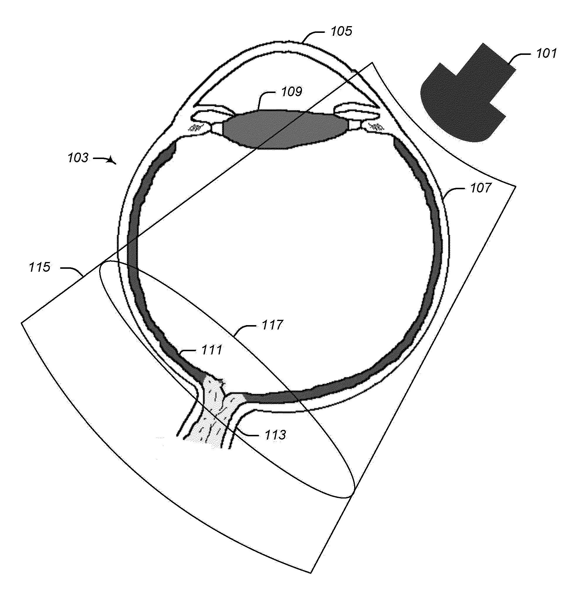
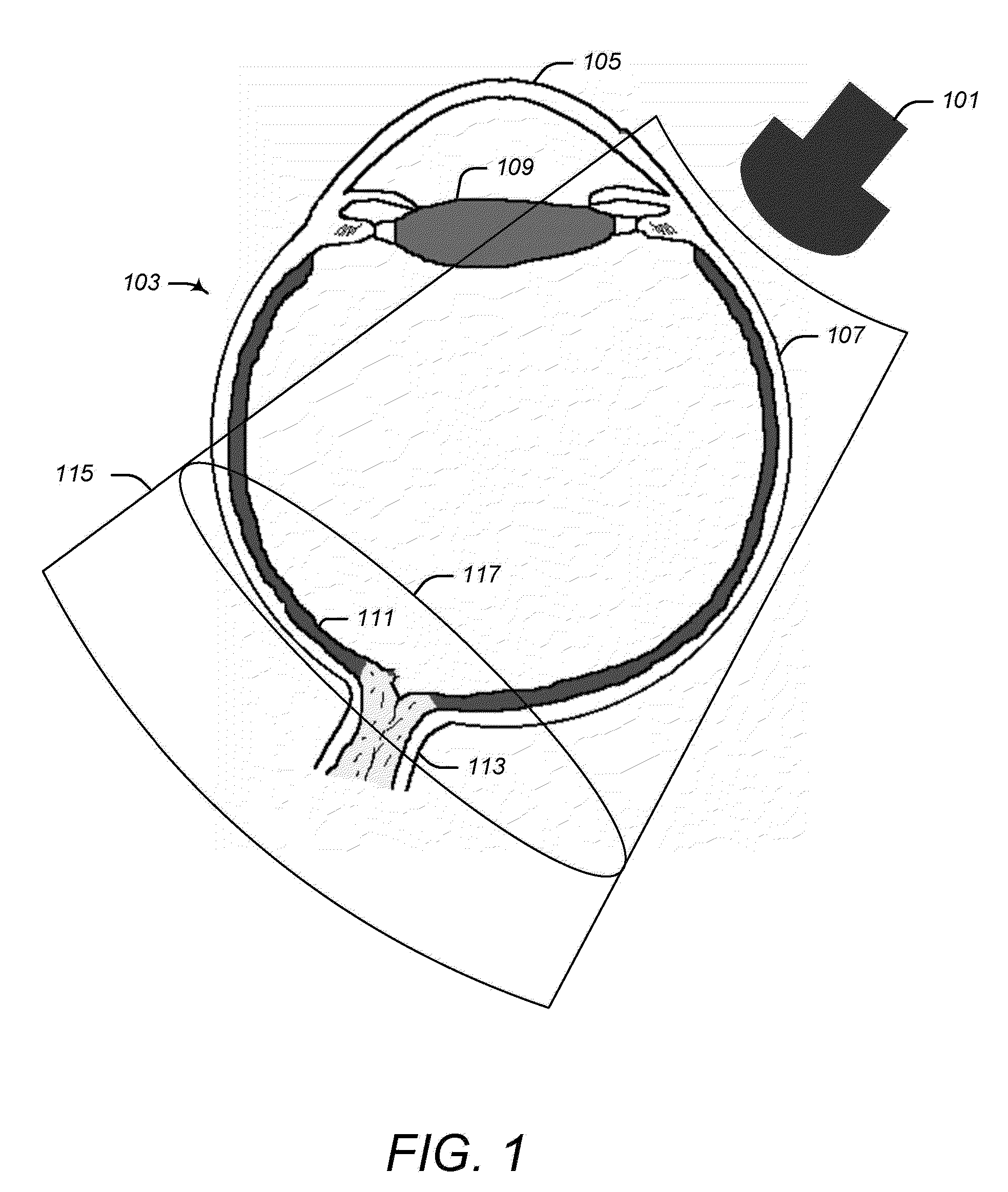
[0037]FIG. 1 illustrates a high frequency convex ultrasonic transducer array positioned to image a portion of a human eye.

[0038]As illustrated in FIG. 1, a high frequency convex ultrasonic transducer array 101 may be positioned in close proximity to a human eye 103, such as next to a portion of the sclera 107 of the human eye 103. The human eye 103 may be approximately one inch in diameter and may include a cornea 105, a lens 109, a retina 111, and an optic nerve 113.

[0039]The ultrasonic transducer array 101 may include a plurality of adjacent ultrasonic transducer elements. Any number of elements may be used. For example, there may be between 60 and 300 adjacent elements. In one e...


PUM


Abstract

A high frequency ultrasonic transducer may include a plurality of adjacent ultrasonic transducer elements. The adjacent transducer elements may be sized and configured so as to resonate at a frequency that is at least 15 MHz. The adjacent transducer elements may collectively form an aperture that is substantially convex along a lateral dimension spanning the cascaded width of the adjacent transducer elements. The aperture may be substantially concave along an elevation spanning the height of each of the transducer elements. The ultrasonic transducer and an associated transmitter system may be configured so as to enable ultrasound that is radiated from the plurality of the transducer elements to be focused on and to scan across locations that are no more than 30 millimeters from the aperture and that span across a field of view of at least 50 degrees without movement of the ultrasonic transducer or tissue during the scanning.

Description

CROSS-REFERENCE TO RELATED APPLICATION[0001]This application is based upon and claims priority to U.S. Provisional Patent Application Ser. No. 60 / 975,616, entitled “SPECIALLY DESIGNED ARRAY TRANSDUCERS FOR HIGH FREQUENCY ULTRASOUND IMAGING,” filed Sep. 27, 2007, attorney docket number 28080-291, the entire contents of which are incorporated herein by reference.STATEMENT REGARDING FEDERALLY SPONSORED RESEARCH[0002]This invention was made with government support under Contract No. P41EB2181 awarded by the National Institutes of Health. The government has certain rights in the invention.BACKGROUND[0003]1. Technical Field[0004]This disclosure relates to ultrasonic transducers and imaging systems and, more particularly, to high frequency ultrasonic transducers and tissue imaging systems.[0005]2. Description of Related Art[0006]High frequency tissue imaging systems may be used to image ophthalmic tissue. These may be based on fixed-focus, single element transducers. Arc scanning may be us...

Claims


Application Information

Patent Timeline
IPC IPC(8): A61N7/00A61B8/00
CPCA61B8/00B06B1/0633G01S15/8929A61B8/488A61B8/06A61B8/10G01S15/8956
Inventor KIM, HYUNG HAMCHANG, JIN HOSHUNG, K. KIRK
Owner UNIV OF SOUTHERN CALIFORNIA
Why Eureka
Try Eureka