Wireless power infrastructure

Active Publication Date: 2010-10-07
IBM CORP
View PDF29 Cites 427 Cited by
  • Summary
  • Abstract
  • Description
  • Claims
  • Application Information

AI Technical Summary

Benefits of technology

[0005]The present invention relates to a system and method for managing and handing off wireless power to a mobile device in a wireless power network. The invention allows a device to hop from one

Problems solved by technology

Unfortunately, such transmissions are not an effective means for power transmission since the radiation disperses the energy in all directions.
Unfortunately, wireless power transmissions ar

Method used


Image

  • Wireless power infrastructure
  • Wireless power infrastructure
  • Wireless power infrastructure

Examples


Embodiment Construction

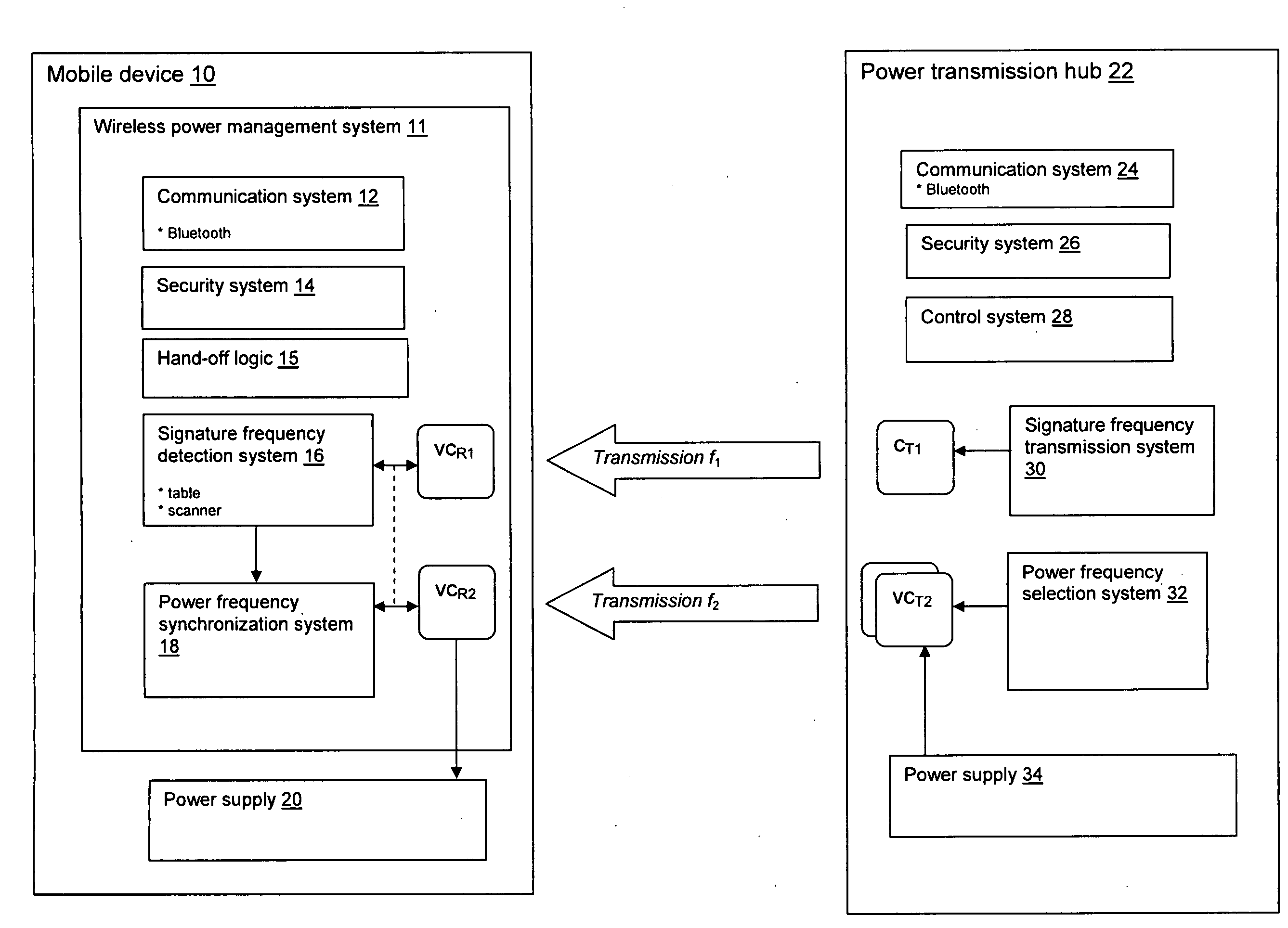
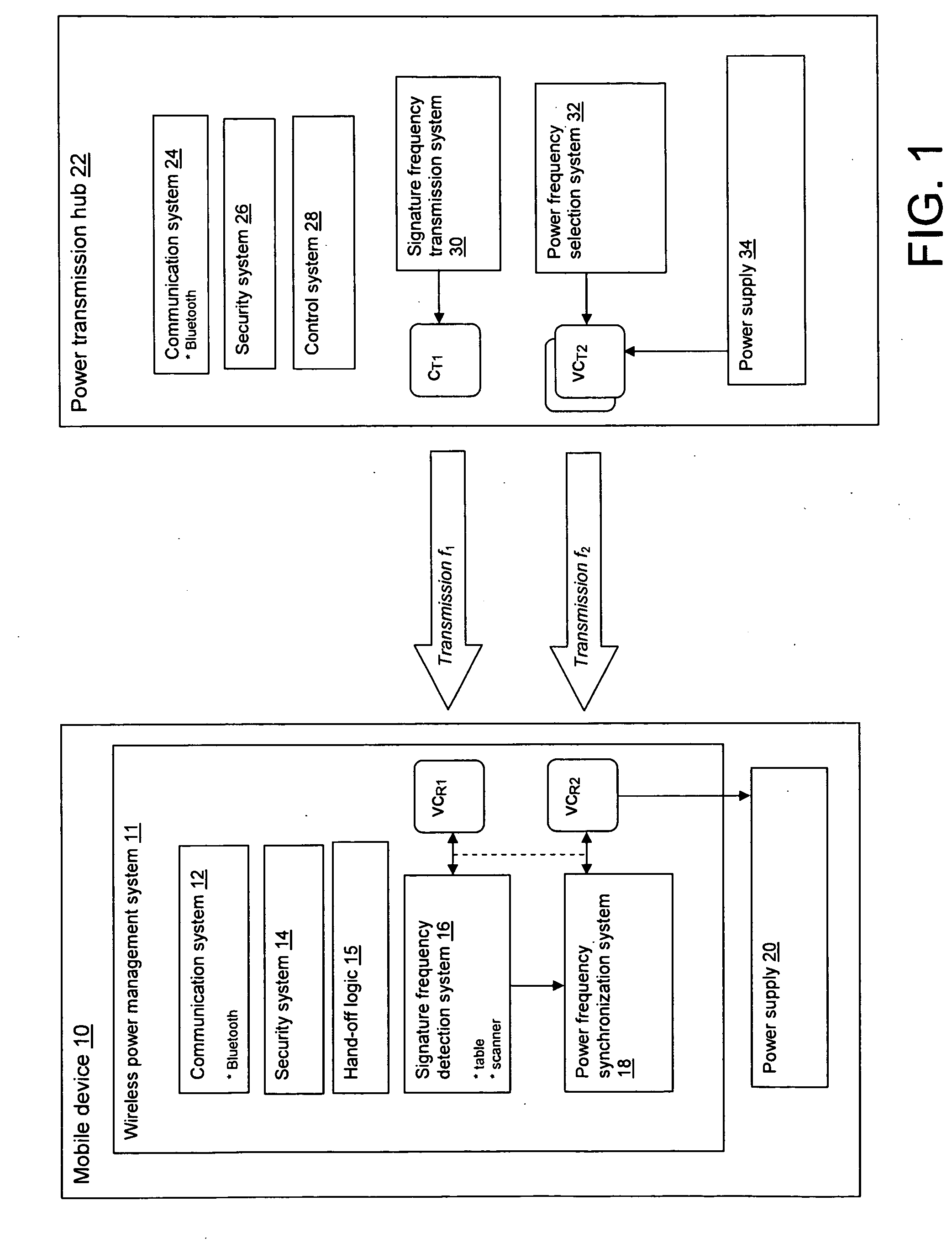
[0018]The present invention provides an implementation for a wireless power network in which wireless power being delivered to one or more devices in the network can be handed off between power transmission hubs (“hubs”). Wireless power may be delivered using any now known or later developed technology, including non-radiative resonant power exchange (“resonant power”). Resonant power provides high efficiency near-field power transmission among devices having matched transmit and receive frequencies.

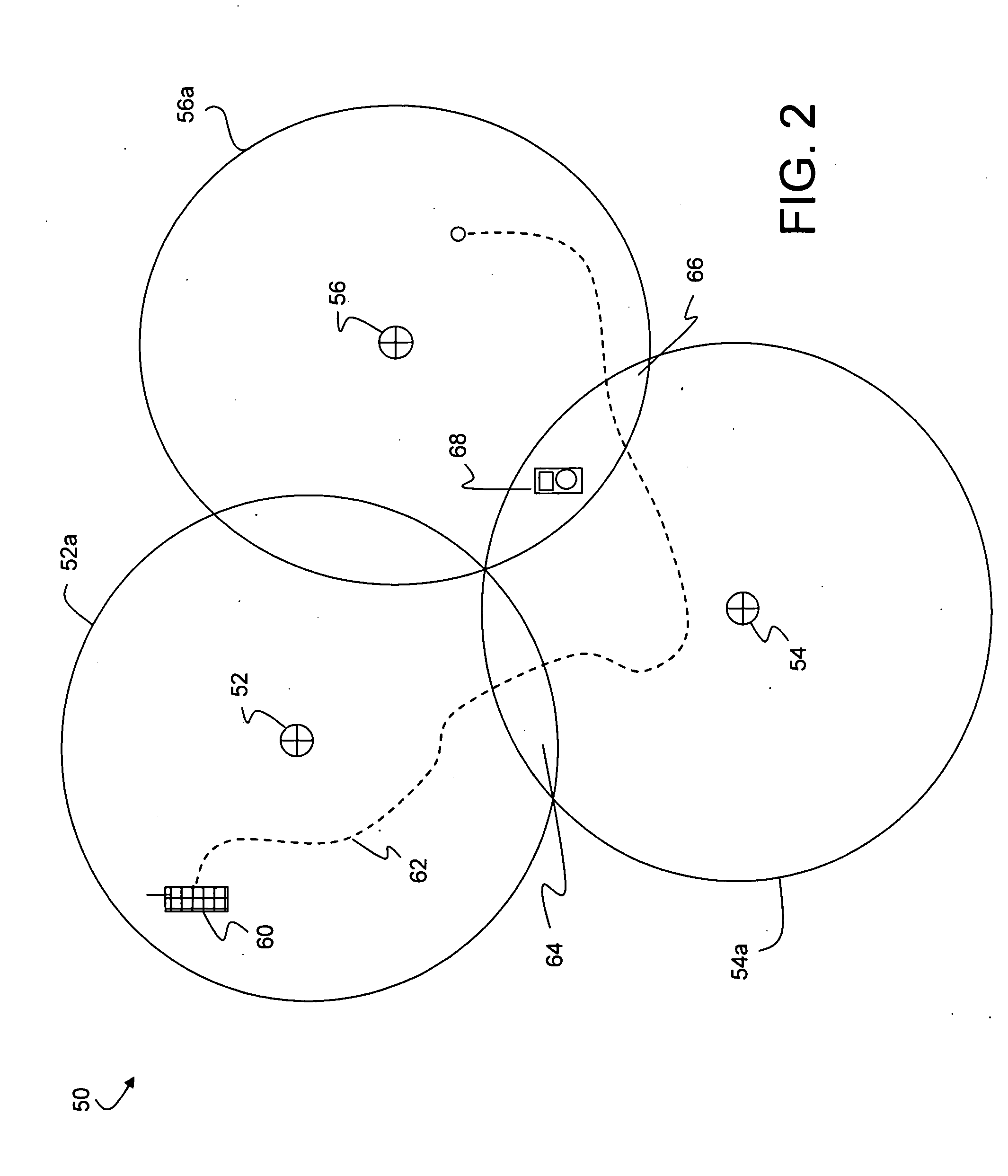
[0019]FIG. 1 depicts an illustrative mobile device 10 and power transmission hub 22 configured to operate within such a wireless power network. As detailed herein, mobile device 10“hops” from one power transmission hub 22 to another based on proximity as mobile device 10 moves throughout the network (See, e.g., FIG. 2). In FIG. 1, mobile device 10 is shown interfacing with proximately located power transmission hub 22.

[0020]Mobile device 10 may comprise any type of portable device that r...


PUM


Abstract

A wireless power infrastructure for delivering wireless power from a wireless network to mobile devices. The infrastructure includes a plurality of power transmission hubs, each hub having: a first capacitor for transmitting a signature frequency for a defined range; and a set of second capacitors, each for transmitting resonant wireless power within the defined range at a selectable frequency. A mobile device for obtaining wireless resonant the plurality of power transmission hubs is also described, and includes: a first variable capacitor for detecting a signature frequency associated with a proximately located power transmission hub; a second variable capacitor for receiving wireless resonant capacitor from the proximately located power transmission hub; and a synchronization system for setting the second variable capacitor to a frequency that is synchronized with a wireless resonant power transmission of the proximately located power transmission hub.

Description

FIELD OF THE INVENTION[0001]This disclosure relates to wireless power, and more particularly relates to a system and method of handing off wireless power to a mobile device from one hub to another in a wireless power network.BACKGROUND OF THE INVENTION[0002]Various methods of transmitting power wirelessly are known, including electromagnetic radiation. Such radiation is commonly used for wireless transmission of information, such as radio waves. Unfortunately, such transmissions are not an effective means for power transmission since the radiation disperses the energy in all directions.[0003]One promising technology for transmitting wireless power is based on using coupled resonant objects. Two resonant objects of the same resonant frequency tend to exchange energy efficiently, while interacting weakly with extraneous off-resonant objects. An example of such a process is described in “Goodbye wires . . . ,” http: / / web.mit.edu / newsoffice / 2007 / wireless-0607.html, Franklin Hadley, Inst...

Claims


Application Information

Patent Timeline
IPC IPC(8): G06F1/28G06F1/32
CPCH02J17/00H02J50/40H02J50/80H02J50/12
Inventor ABRAMO, KEITHKINLAW, JOSHUA R.LEONG, JOSEPH C.RODRIGUEZ, ADRIAN X.WOLOSCHYN, GREGORY B.
Owner IBM CORP
Why Eureka
Try Eureka