Ride height leveling control for dual air spring configuration

a technology of air springs and ride heights, applied in the field of air suspension systems, can solve the problems of vehicle oscillation, difficulty in smooth and repeatable adjustment of vehicle ride heights,

Inactive Publication Date: 2010-10-14
ARVINMERITOR TECH
View PDF6 Cites 20 Cited by
  • Summary
  • Abstract
  • Description
  • Claims
  • Application Information

AI Technical Summary

Problems solved by technology

Vehicles equipped with suspension systems that have multiple airbags at each corner have difficulty adjusting vehicle ride height in a smooth and repeatable ma...

Method used


Image

  • Ride height leveling control for dual air spring configuration
  • Ride height leveling control for dual air spring configuration
  • Ride height leveling control for dual air spring configuration

Examples


Embodiment Construction

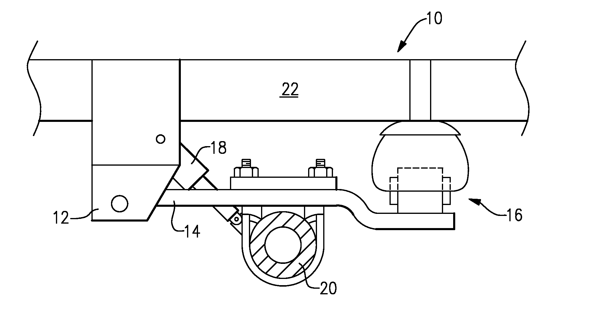
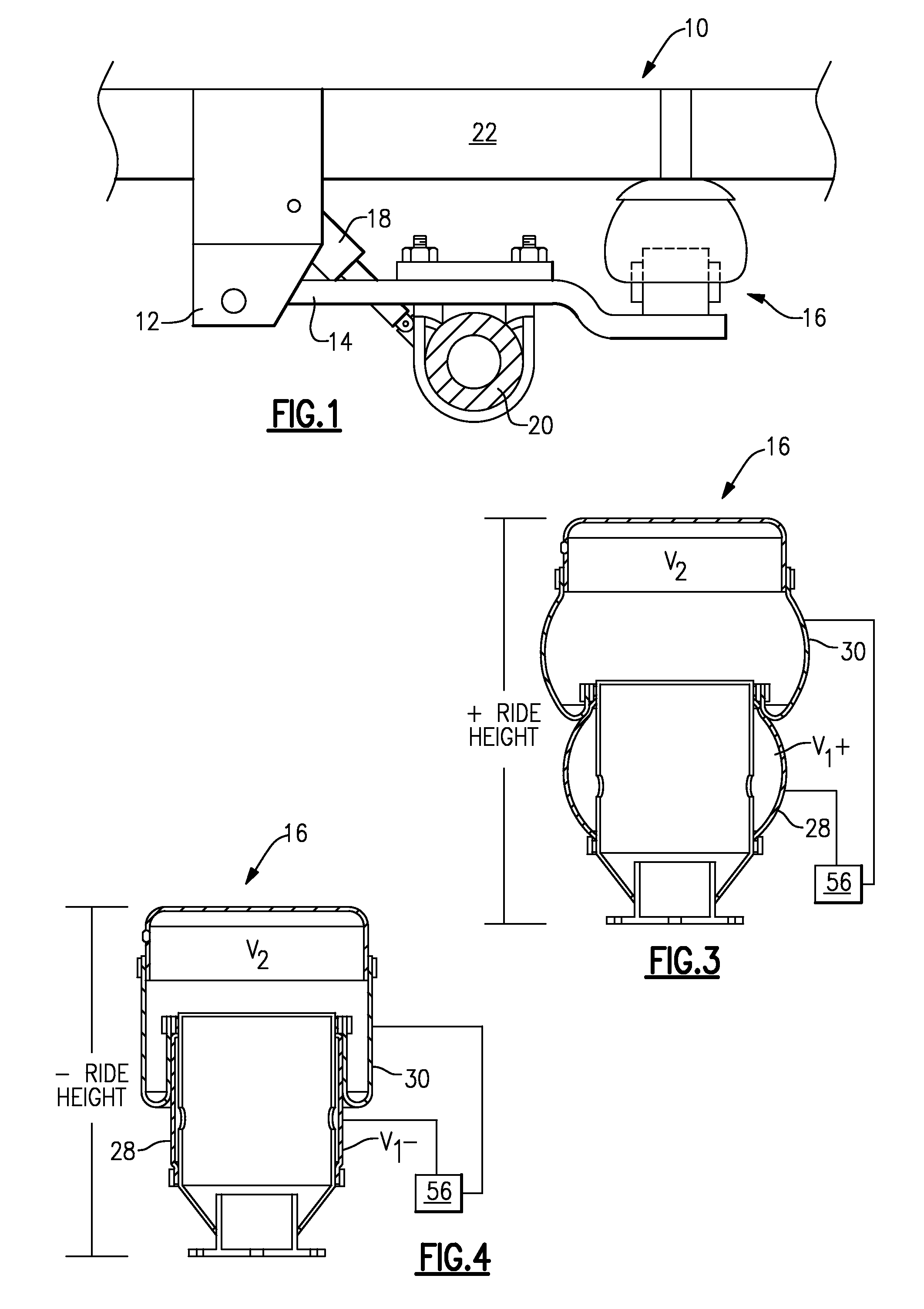
[0013]FIG. 1 illustrates an air suspension system 10 for a vehicle. The air suspension system 10 generally includes a bracket 12, a longitudinal member 14, an air spring assembly 16, a damper 18, and an axle assembly 20. The air suspension system 10 is fixed to a frame or chassis of the vehicle (shown schematically at 22). The longitudinal member 14 could comprise a suspension arm, for example, and the axle assembly 20 could comprise any type of axle, such as a drive axle, non-drive axle, trailer axle, etc. The axle assembly 20 extends between laterally spaced wheels (not shown). It should be understood that the air suspension system 10 includes a longitudinal member 14, an air spring assembly 16, and a damper 18 at each lateral end of the axle assembly 20.

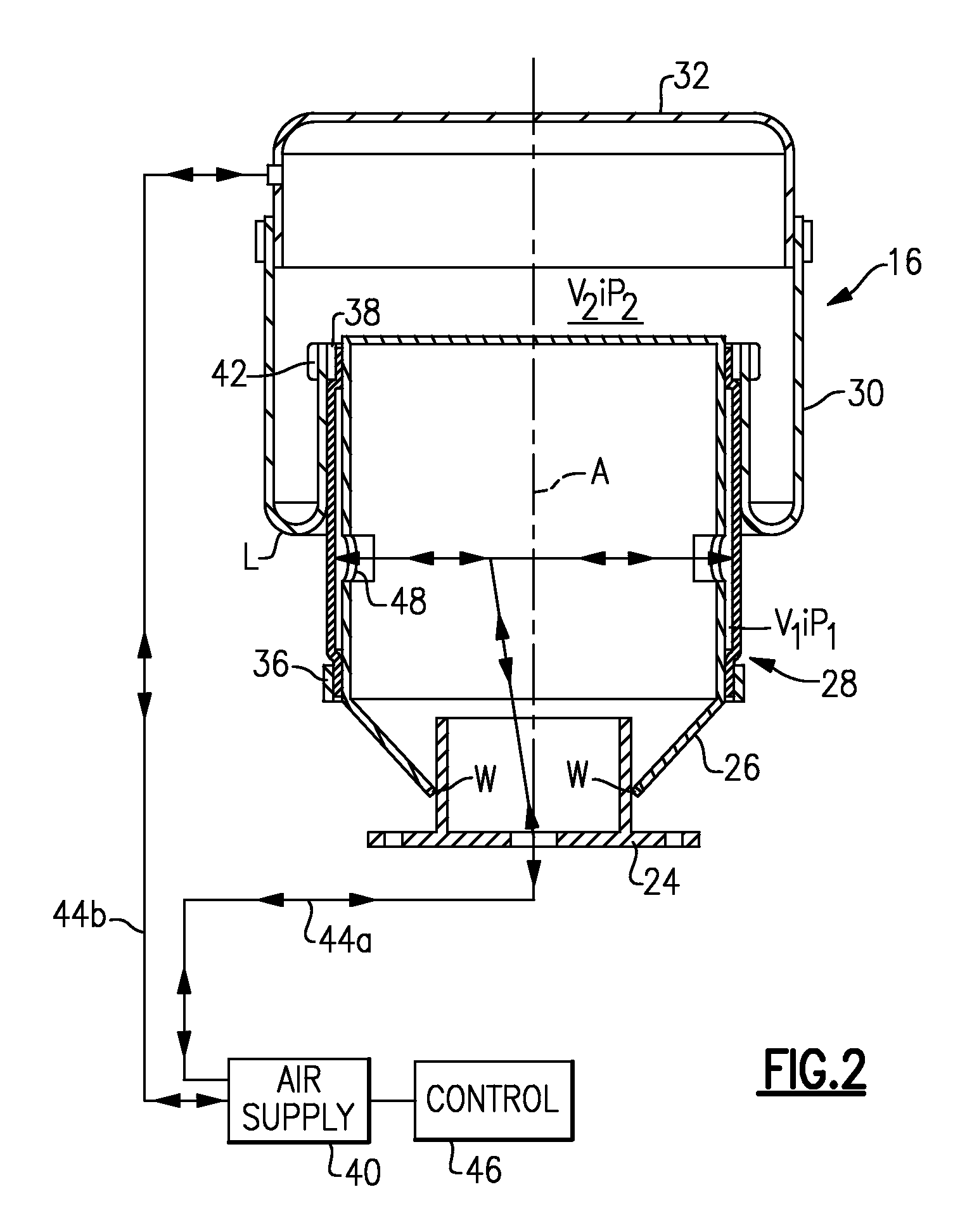
[0014]Referring to FIG. 2, the air spring assembly 16 is illustrated in cross-section. The air spring assembly 16 is defined along a central vertical axis A and includes a lower mount 24 (illustrated schematically), a piston suppo...


PUM


Abstract

An air suspension system is configured to adjust and maintain a desired vehicle ride height and spring rate. The air suspension system includes a plurality of air spring assemblies that each include a piston airbag and a primary airbag mounted around the piston airbag. A controller receives ride height input data and adjusts pressures within the primary and piston airbags until the desired ride height and spring rate is achieved. The controller accommodates for system hardware differences by varying flow rates into and out of the primary and piston airbags relative to each other.

Description

TECHNICAL FIELD[0001]This invention generally relates to an air suspension system that is configured to actively adjust and maintain a desired vehicle ride height and spring rate as needed.BACKGROUND OF THE INVENTION[0002]Air suspensions utilize air springs to provide desired output characteristics, such as ride comfort, maintaining vehicle height and vehicle performance for example. One known active air suspension uses an air spring assembly that includes a primary airbag mounted around a piston airbag such that the piston airbag provides a rolling surface for the primary airbag. A change in piston airbag volume changes an effective piston area of the primary airbag. A relatively small change in the effective piston area provides a change in a spring rate of the air spring assembly. The pressures in the piston airbag and the primary airbag are selectively controlled to provide infinite variation in spring rates. The smaller volume of the piston airbag relative to the larger volume ...

Claims


Application Information

Patent Timeline
IPC IPC(8): B60G17/033B60G17/052B60G17/056B60G17/015
CPCB60G11/28B60G2800/914B60G17/04B60G17/0485B60G17/0521B60G2202/152B60G2202/314B60G2202/412B60G2400/252B60G2500/201B60G2500/2021B60G2500/22B60G2500/30B60G2600/182B60G2600/70B60G2800/912B60G17/0155
Inventor HONIG, JONATHAN L.VANRAAPHORST, DAVID A.
Owner ARVINMERITOR TECH
Why Eureka
Try Eureka