Stator for external rotor motor

a rotor motor and rotor joint technology, applied in the direction of electrical equipment, dynamo-electric machines, supports/enclosements/casings, etc., can solve the problems of affecting normal operation, affecting the normal operation of the rotor joint, and damage to other components, so as to improve the work life and improve the connection. , the effect of increasing the work li

Active Publication Date: 2010-10-14
ZHONGSHAN BROAD OCEAN
View PDF4 Cites 14 Cited by
  • Summary
  • Abstract
  • Description
  • Claims
  • Application Information

AI Technical Summary

Benefits of technology

[0025]Advantages of the invention comprise: 1) the patch board is disposed above one end of the stator core, the fastening device is disposed at the top of the patch board, and the weld-connecting portion comprising the head of the stator winding and the power wire is disposed in the fastening device, which improves connection between the head of the stator winding and the power wire; 2) the head of the stator winding and the power wire are orderly distributed in the motor and do not contact with other components of the motor, which ensures normal operation of the motor and increases work life thereof; 3) the invention features reasonable distribution and compact structure; and 4) the fastening device features simple structure, convenient use, and low production cost.

Problems solved by technology

However, there are several problems with the conventional stator: firstly, the solder joint is easy to be broken; secondly, connection between the head of the stator winding and the power wire is unstable, and the power wire is easy to be detached; thirdly, there is no fixing device at the solder joint between the head of the stator winding and the power wire, and the head of the stator winding and the power wire are disorderly distributed in the motor and may contact with other components of the motor, which affects normal operation thereof, damages other components thereof, and reduces work life thereof.

Method used


Image

  • Stator for external rotor motor
  • Stator for external rotor motor
  • Stator for external rotor motor

Examples


Embodiment Construction

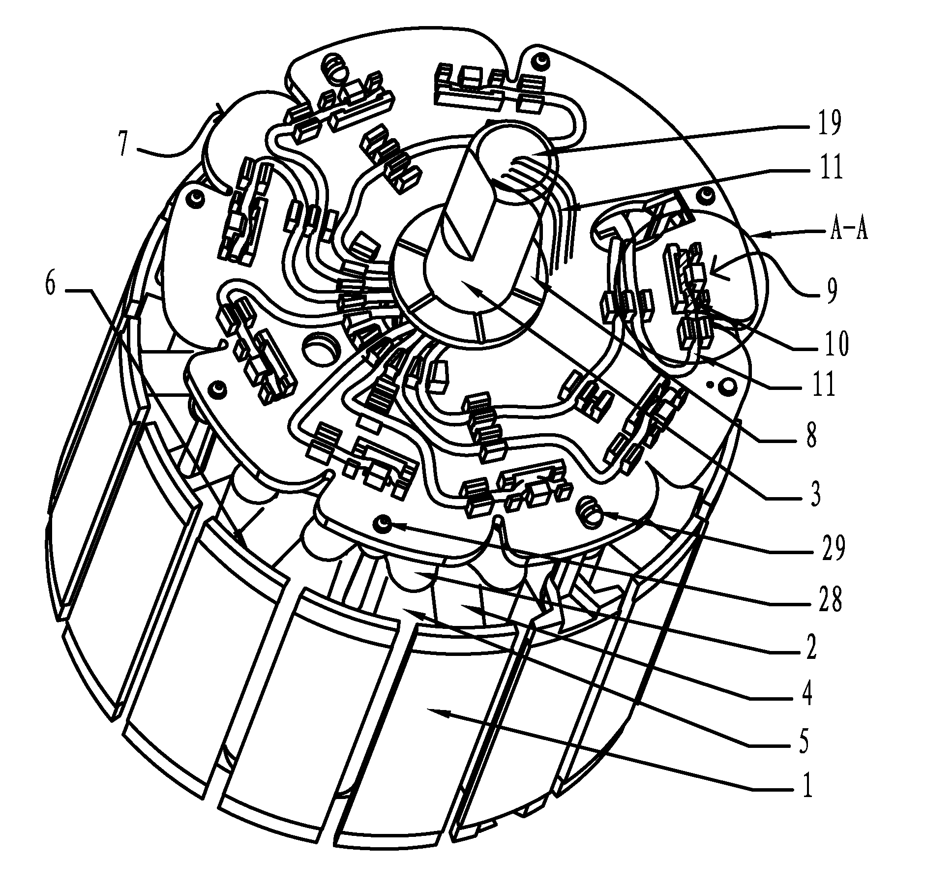
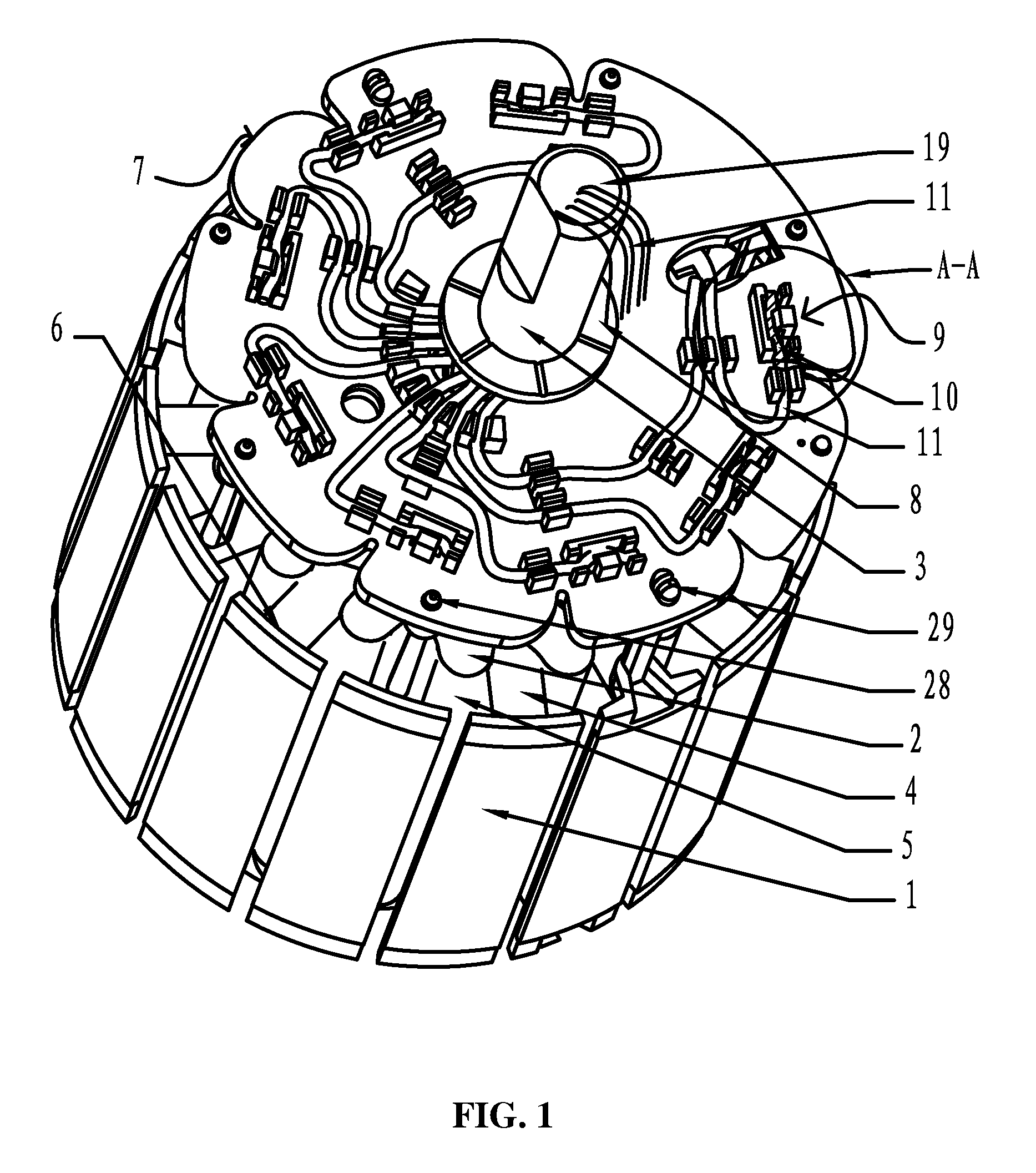
[0032]As shown in FIG. 1, A stator for an external rotor motor of the invention comprises a stator core 1 having multiple teeth 4 and a shaft 3, a stator winding 2, multiple slots 5, a pair of end plates 6, a patch board 7 having a first through hole 8, a power wire 11, and a fastening device 9.

[0033]The shaft 3 is disposed at the center of the stator core 1.

[0034]The slot 5 is formed between adjacent teeth 4 of the stator core 1, and passes through the first through hole 8 of the patch board 7.

[0035]The stator winding 2 is received in the slot 5 and wrapped around the teeth 4 of the stator core 1.

[0036]Insulators are injected in one end of the stator core 1 and in the slot 5.

[0037]The end plate 6 is formed via insulators on one end of the stator core 1.

[0038]The patch board 7 is disposed above one of the end plates 6.

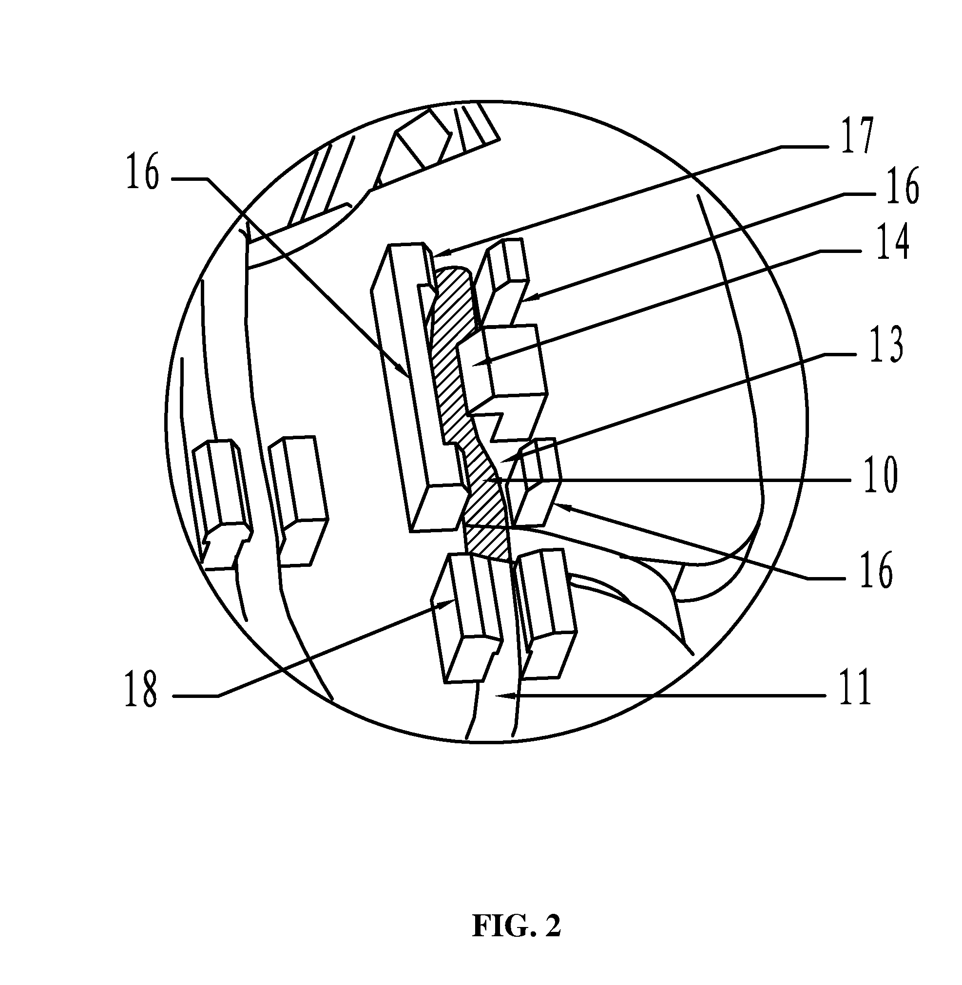
[0039]A head of the stator winding 2 is welded with the power wire 11 to form a weld-connecting portion 10.

[0040]The fastening device 9 is disposed at the top of the p...


PUM


Abstract

A stator for an external rotor motor, containing at least a stator core (1) having multiple teeth (4) and a shaft (3), a stator winding (2), multiple slots (5), a pair of end plates (6), a patch board (7) having a first through hole (8), a power wire (11), and a fastening device (9). The shaft (3) is disposed at the center of the stator core (1). The slot (5) is formed between adjacent teeth (4) of the stator core (1). The stator winding (2) is received in the slot (5) and wrapped around the teeth (4). The patch board (7) is disposed above one of the end plates (6). The shaft (3) passes through the first through hole (8) of the patch board (7). The fastening device (9) is disposed at the top of the patch board (7) and operates to fix the weld-connecting portion (10).

Description

CROSS-REFERENCE TO RELATED APPLICATIONS[0001]Pursuant to 35 U.S.C. §119 and the Paris Convention Treaty, this application claims the benefit of Chinese Patent Application No. 200920054631.6 filed on Apr. 13, 2009, the contents of which are incorporated herein by reference.BACKGROUND OF THE INVENTION[0002]1. Field of the Invention[0003]The invention relates to a stator, and more particularly to a stator for an external rotor motor.[0004]2. Description of the Related Art[0005]A conventional stator for an external rotor motor comprises a stator winding and a power wire. A head of the stator winding is connected to the power wire via welding, and insulators are injected on a solder joint therebetween. However, there are several problems with the conventional stator: firstly, the solder joint is easy to be broken; secondly, connection between the head of the stator winding and the power wire is unstable, and the power wire is easy to be detached; thirdly, there is no fixing device at the...

Claims


Application Information

Patent Timeline
Patent Type & Authority Applications(United States)
IPC IPC(8): H02K11/00
CPCH02K3/50H02K5/225H02K2203/03H02K11/0089H02K11/0047H02K11/25H02K11/40
Inventor WANG, XIONGCHENG
Owner ZHONGSHAN BROAD OCEAN
Why Eureka
Try Eureka