Remote Lighting Control System

Active Publication Date: 2010-10-14
EYE LIGHTING SYST CORP +1
View PDF2 Cites 63 Cited by
  • Summary
  • Abstract
  • Description
  • Claims
  • Application Information

AI Technical Summary

Benefits of technology

[0043]As described above, the electronic ballast provided for each discharge lamp has a specialized transceiver. When one of the transceivers receives a control command from the outside, the transceiver sends the control information based on the received control command to the associated controller and also sends the received control command further to allow transfer to the other electronic ballasts. This structure enables remot

Problems solved by technology

Installation of the signal lines takes a great deal of labor and cost.
Since the control panel is not p

Method used


Image

  • Remote Lighting Control System
  • Remote Lighting Control System
  • Remote Lighting Control System

Examples


Embodiment Construction

[0050]A remote lighting control system according to a preferred embodiment of the present invention will be described below with reference to the drawings.

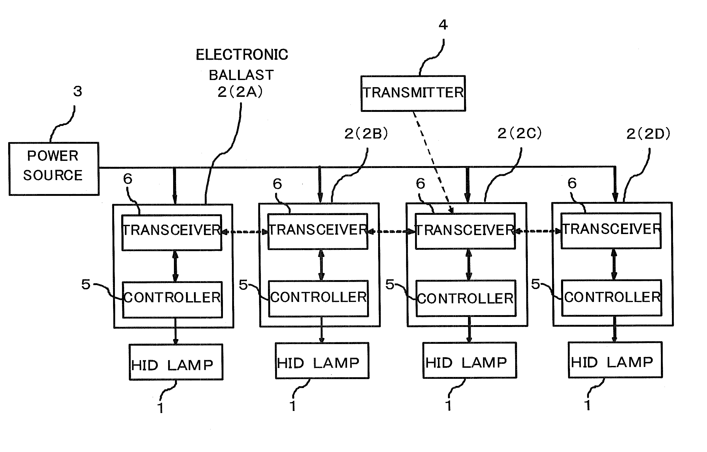
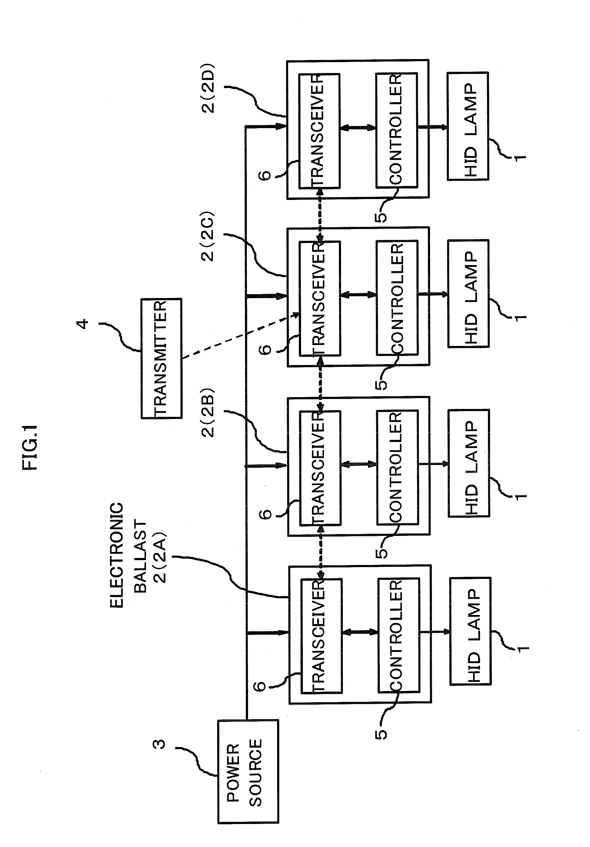
[0051]As shown in FIG. 1, the remote lighting control system performs remote control of lighting of a plurality of discharge lamps 1. The system includes the discharge lamps 1 such as high-intensity discharge (HID) lamps, electronic ballasts 2 provided for respective discharge lamps, a power source 3 for supplying power to the electronic ballasts 2, and a transmitter 4 for transmitting a control command to the electronic ballasts 2. Lighting control of the discharge lamps 1 includes turning on, turning off, and dimming of the discharge lamps 1, control after detection of extinction of the discharge lamps, control based on lighting frequency, and control based on accumulated lamp operation time, for instance.

[0052]The power source 3 and the electronic ballasts 2 are connected by power supply cables, through which power is supplied ...


PUM


Abstract

A remote lighting control system is for remote lighting control of a plurality of discharge lamps. This system has the installed electronic ballasts of each discharge lamp. Each electronic ballast has a transceiver and a controller, the transceiver exchanges control information with the controller. The control command contains the identifiable information to specify one of a plurality of electronic ballasts. When the transmitter is received the control command, the transceiver transfers the received control command to other electronic ballasts further. Moreover, if the control command is the one that the identifiable information specifies own ballasts, the control information based on the received control command is send to own controller, and the controller control the discharge lamp. According to this system, when a lot of lamps was arranged the factory etc. comparatively widely, the user's remote control is not limited to the narrow scope.

Description

RELATED APPLICATIONS[0001]This application claims the priority of Japanese Patent Application No. 2009-095197 filed on Apr. 28, 2009, which are incorporated herein by reference.BACKGROUND OF THE INVENTION[0002]1. Field of the Invention[0003]The present invention relates to remote control systems for a plurality of discharge lamps placed in a relatively wide area such as a factory or a shopping mall.[0004]2. Prior Art[0005]In one conventionally known control system for a plurality of discharge lamps, a control panel and electronic ballasts provided respectively for the plurality of discharge lamps are connected by wires (Japanese laid-open disclosure public patent bulletin No. 2002-75683).[0006]Another known system uses a remote controller 116 that can send an infrared control signal for remote control of a control panel 106, as shown in FIG. 6. The control panel 106 has an infrared light receiving unit 114 and turns on each discharge lamp 104 through an electronic ballast 110 on the...

Claims


Application Information

Patent Timeline
IPC IPC(8): H05B41/36
CPCH05B37/034H05B37/0272H05B47/22H05B47/19
Inventor UMEZAWA, YOSHIHISATERAYAMA, ICHIROUIKEDA, MASAKAZUTAINAKA, YUSUKE
Owner EYE LIGHTING SYST CORP
Why Eureka
Try Eureka