Video display apparatus, video viewing glasses, and system comprising the display apparatus and the glasses

a video display and video technology, applied in the field of video display apparatus and video viewing glasses, can solve the problems of potentially cutting off of shutter glasses, revealing a technology for controlling a video display apparatus and/or video viewing glasses, etc., and achieve the effect of improving video viewing technology

Inactive Publication Date: 2010-10-14
PANASONIC INTELLECTUAL PROPERTY MANAGEMENT CO LTD
View PDF21 Cites 45 Cited by
  • Summary
  • Abstract
  • Description
  • Claims
  • Application Information

AI Technical Summary

Benefits of technology

[0002]The present invention relates to a technology for allowing a viewer to view a video displayed on a video display apparatus through video viewing glasses, and more particularly to a technology for allowing a viewer to view a video on a video display apparatus through video viewing glasses configured to select a video displayed on the video display apparatus.

Problems solved by technology

A signal indicating a switching timing between videos for left and right eyes from a stereoscopic video display apparatus to liquid crystal shutter glasses may be potentially cut off for some reason.
Japanese Unexamined Patent Publication No. 2000-36969 discloses the switching operation between left and right liquid crystal shutters during a non-display period in a sub-field on a PDP to be used as a video display apparatus, but does not disclose a technology for controlling a video display apparatus and / or video viewing glasses, taking an influence on video display by a video display apparatus (e.g. how the switching display between a left eye video and a right eye video affect an image to be viewed) into account .

Method used


Image

  • Video display apparatus, video viewing glasses, and system comprising the display apparatus and the glasses
  • Video display apparatus, video viewing glasses, and system comprising the display apparatus and the glasses
  • Video display apparatus, video viewing glasses, and system comprising the display apparatus and the glasses

Examples


first embodiment

[0034]

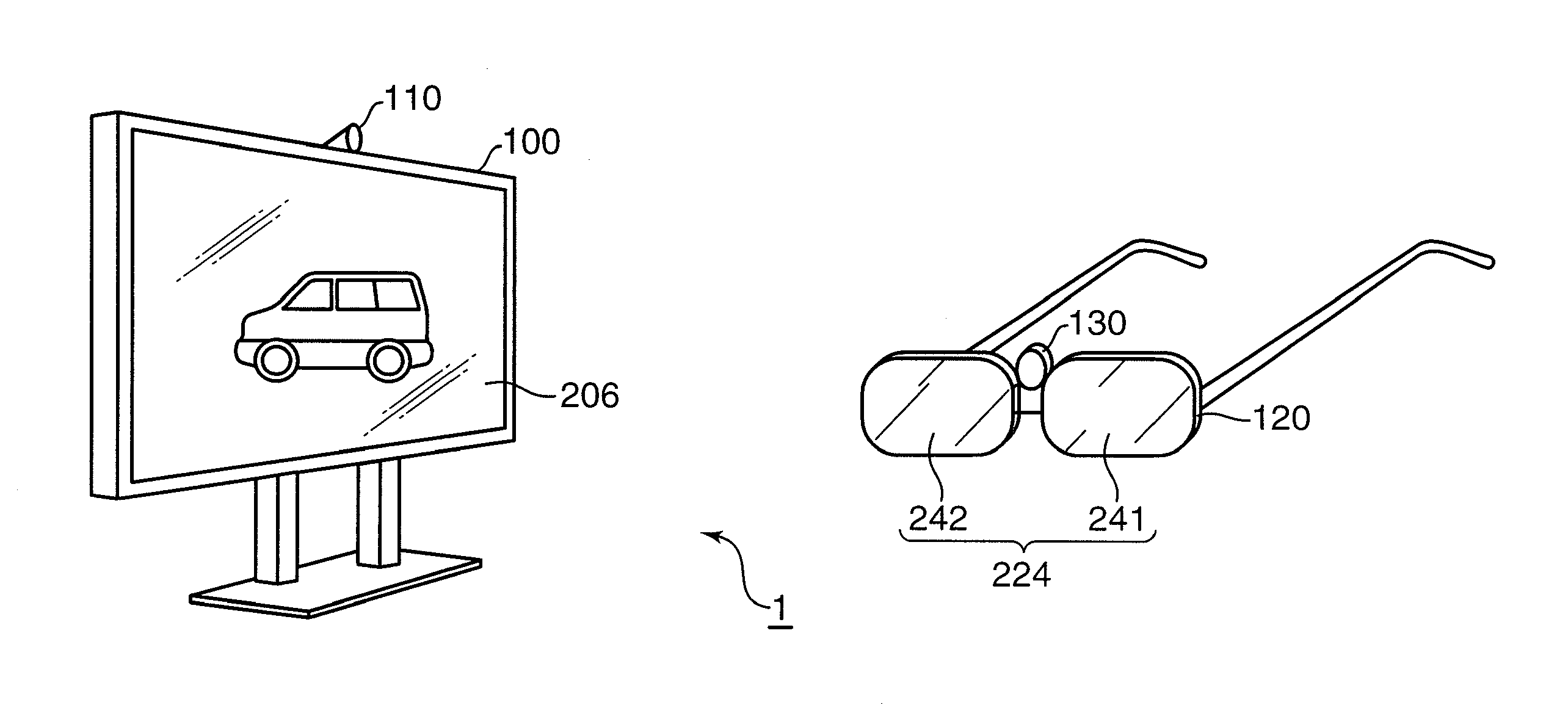
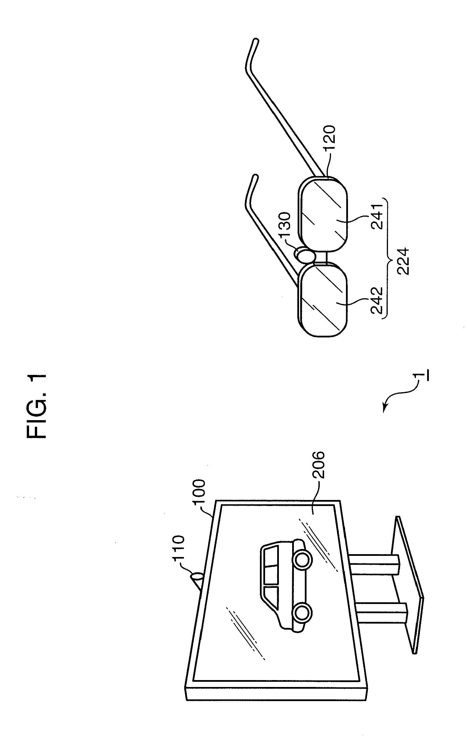
[0035]FIG. 1 is a diagram showing a video display system comprising a video display apparatus, and video viewing glasses to be used in viewing a video displayed on the video display apparatus. In this embodiment, a viewer is allowed to visually recognize a stereoscopic video by viewing a video to be displayed on a display plane of the video display apparatus through the video viewing glasses.

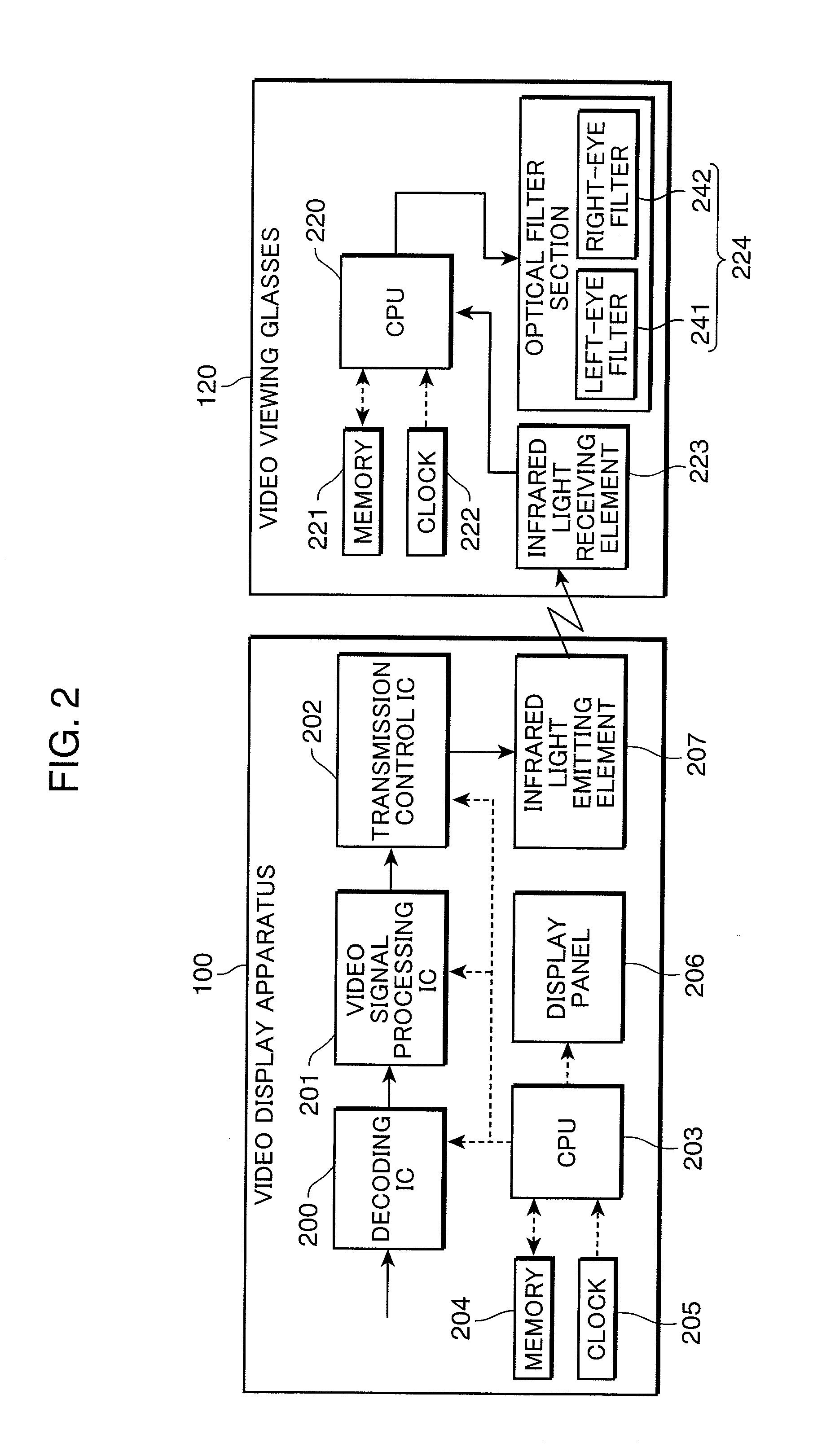
[0036]A video display system 1 shown in FIG. 1 includes a video display apparatus 100 for displaying a video, and video viewing glasses 120. The video display apparatus 100 includes a display panel 206. A left-eye video and a right-eye video are alternately displayed on the display panel 206. The left-eye video and the right-eye video to be displayed on the video display apparatus 100 may contain contents different from each other by a parallax in the viewer's eyes.

[0037]The video viewing glasses 120 substantially looks like a vision correction eyeglasses as a whole. The video viewing glas...

second embodiment

[0157]The second embodiment is different from the first embodiment only in a synchronizing signal to be transmitted from a video display apparatus 100 to video viewing glasses 120. Since the other configuration of the second embodiment is substantially the same as the corresponding configuration of the first embodiment, description thereof is omitted herein.

[0158]FIG. 15 is a diagram showing a control using three kinds of synchronizing signals different from each other. A video frame shown in the section (A) in FIG. 15 is a stereoscopic video which is supposed to be perceived as a three-dimensional video (see FIGS. 5 and 6). The example shown in FIG. 15 is different from the first embodiment only in the synchronizing signals shown in the section (B) in FIG. 15. The section (B) in FIG. 15 shows three kinds of synchronizing signals 1501, 1502, and 1503 having waveforms different from each other. Similarly to the pulse waveform described referring to FIG. 8, a synchronizing signal anal...

third embodiment

[0170]In the first and the second embodiments, the video display apparatus 100 displays a video for allowing the viewer to view a stereoscopic video. In this embodiment, a video display apparatus 100 displays a video for allowing the viewer to view two moving picture videos representing contents different from each other.

[0171]FIG. 18 is a diagram showing a control for allowing the viewer to view two moving picture videos representing contents different from each other. FIG. 19 is a diagram showing an example of videos in a first video frame and a second video frame shown in the section (A) in FIG. 18. In the section (A) in FIG. 18, a first video and a second video to be displayed on a video displayer 303 of the video display apparatus 100 are switched every one frame. In the control shown in FIG. 18, the synchronizing signals shown in FIG. 18 are indicated with the same reference numerals as those used in FIG. 15 because synchronizing signals to be transmitted from the video displa...


PUM


Abstract

Provided is a video system equipped with a video display apparatus, and video viewing glasses for use in viewing a video displayed on the video display apparatus. The video display apparatus includes: a display section for displaying a video; a synchronizing signal generator for generating an external synchronizing signal for notifying an end of displaying a frame constituting the video in synchronism with the video; and a synchronizing signal transmitter for transmitting the external synchronizing signal to the video viewing glasses. The video viewing glasses include: a synchronizing signal receiver for receiving the external synchronizing signal; an optical filter section having a pair of optical filters for adjusting amounts of light to be transmitted to a left eye and a right eye of a viewer, respectively; and an optical filter controller for controlling the optical filter section based on the external synchronizing signal.

Description

BACKGROUND OF THE INVENTION[0001]1. Field of the Invention[0002]The present invention relates to a technology for allowing a viewer to view a video displayed on a video display apparatus through video viewing glasses, and more particularly to a technology for allowing a viewer to view a video on a video display apparatus through video viewing glasses configured to select a video displayed on the video display apparatus.[0003]2. Description of the Related Art[0004]A signal indicating a switching timing between videos for left and right eyes from a stereoscopic video display apparatus to liquid crystal shutter glasses may be potentially cut off for some reason. Japanese Unexamined Patent Publication No. H11-98538 discloses a technology for solving problems resulting from the signal cut-off such as disable stereoscopic viewing and screen flickering. The liquid crystal shutter glasses disclosed in Japanese Unexamined Patent Publication No. H11-98538 internally generates a signal for sel...

Claims


Application Information

Patent Timeline
Patent Type & Authority Applications(United States)
IPC IPC(8): H04N13/04G02B27/22
CPCH04N13/0438H04N13/0497H04N2213/008G09G2320/0257G09G3/28G09G2310/065G09G3/003H04N13/398H04N13/341
Inventor MIHARA, KAZUHIROINOUE, SHUJIMITANI, HIROSHIINOE, MASANOBUMATSUMOTO, KEIZOUOKAMOTO, KAZUOSAIGO, KATSUO
Owner PANASONIC INTELLECTUAL PROPERTY MANAGEMENT CO LTD
Why Eureka
Try Eureka