
Laser drive

Inactive Publication Date: 2010-10-14
SONY CORP
View PDF3 Cites 10 Cited by
  • Summary
  • Abstract
  • Description
  • Claims
  • Application Information

AI Technical Summary

Benefits of technology

[0021]The present invention has been made in order to solve the problems described above, and it is therefore desirable to provide a laser driver with which rising and fall characteristics of a vertical cavity surface emitting laser can be improved without complicating a circuit configuration.
[0023]As set forth hereinabove, according to an embodiment of the present invention, since the drive current is supplied to the laser in accordance with the voltage drive for the first time period from the start of the light emission time period of the laser, it is possible to realize the high-speed rising characteristics (TR characteristics) without being influenced by the parasitic capacitance parasitic in the laser. In addition, since the laser driver has the feedback loop for monitoring the drive current in real time during the voltage drive until the end of the subsequent light emission time period, and making feedback to the drive voltage, the drive current can be held constant irrespective of the fluctuation of the light emission resistance. Moreover, the second emitter follower is operated to discharge the electric charges accumulated in the laser for the second time period after the end of the light emission time period of the laser, the electric charge drawing characteristics are enhanced, and thus it is possible to realize the high-speed fall characteristics (TF characteristics).

Problems solved by technology

As a result, there is encountered such a problem that the control becomes complicated, and thus the circuit scale becomes large.
As a result, the circuit scale is compelled to become large, and thus those different control systems need to be smoothly switched over to each other, so that the control is compelled to become complicated.
However, with the output stage composed of only the emitter follower, it may be difficult to solve the problems about the change in amount of light emission following the change in light emission resistance Ract, the nonuniformity of the amount of light emission due to the dispersion of the light emission resistance Ract between the channels, and the blunting of the OFF-characteristics of the light emission at the time of turn-OFF of the vertical cavity surface light emitting laser.

Method used


Image

  • Laser drive
  • Laser drive
  • Laser drive

Examples


Embodiment Construction

[0031]Hereinafter, an embodiment of the present invention will be described in detail with reference to the accompanying drawings. It is noted that the description will now be given in accordance with the following order.

[0032]1. Basic Configuration of Laser Driver

[0033]2. Concrete Circuit Configuration of Laser Driver

1. Basic Configuration of Laser Driver

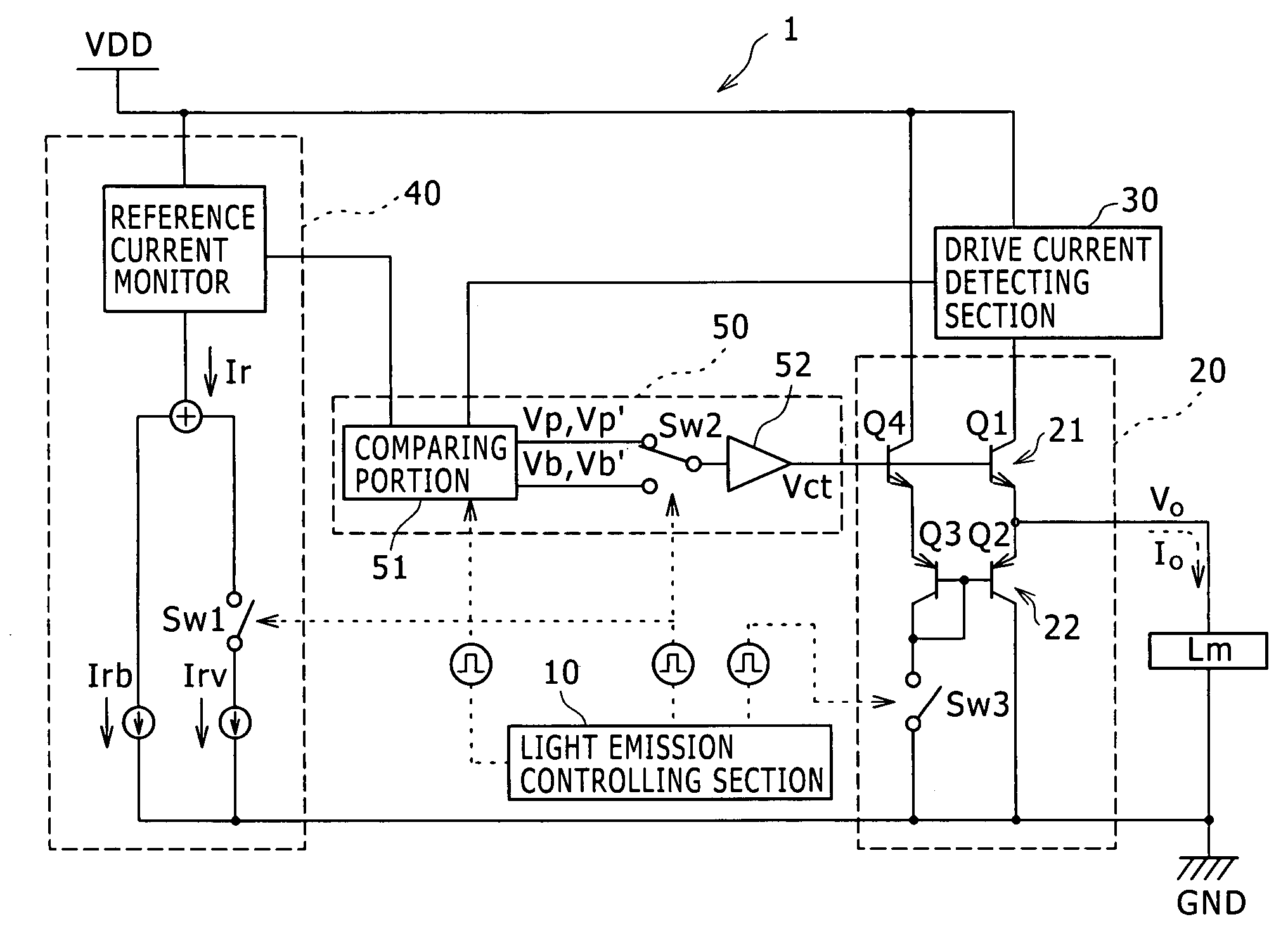
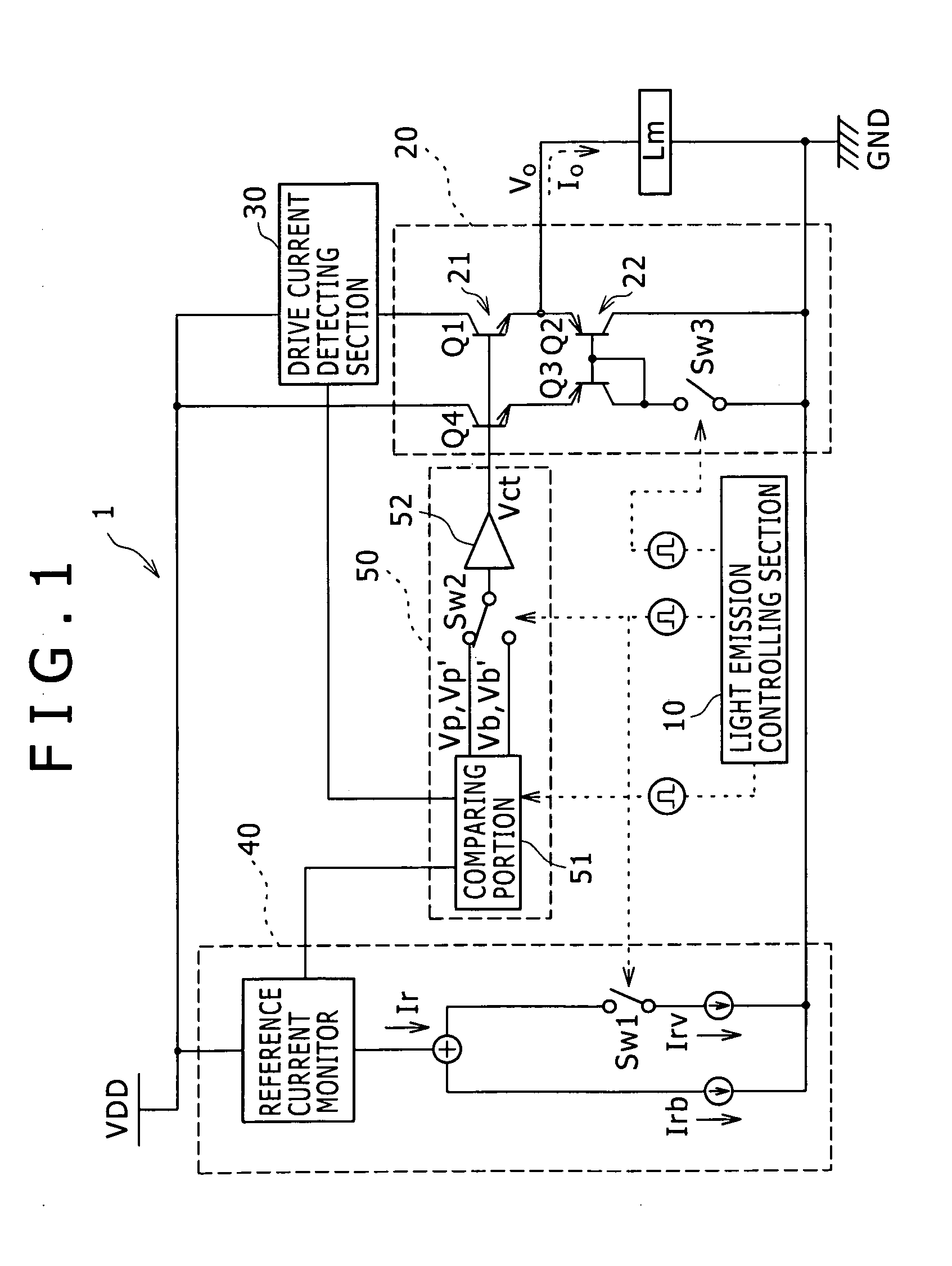
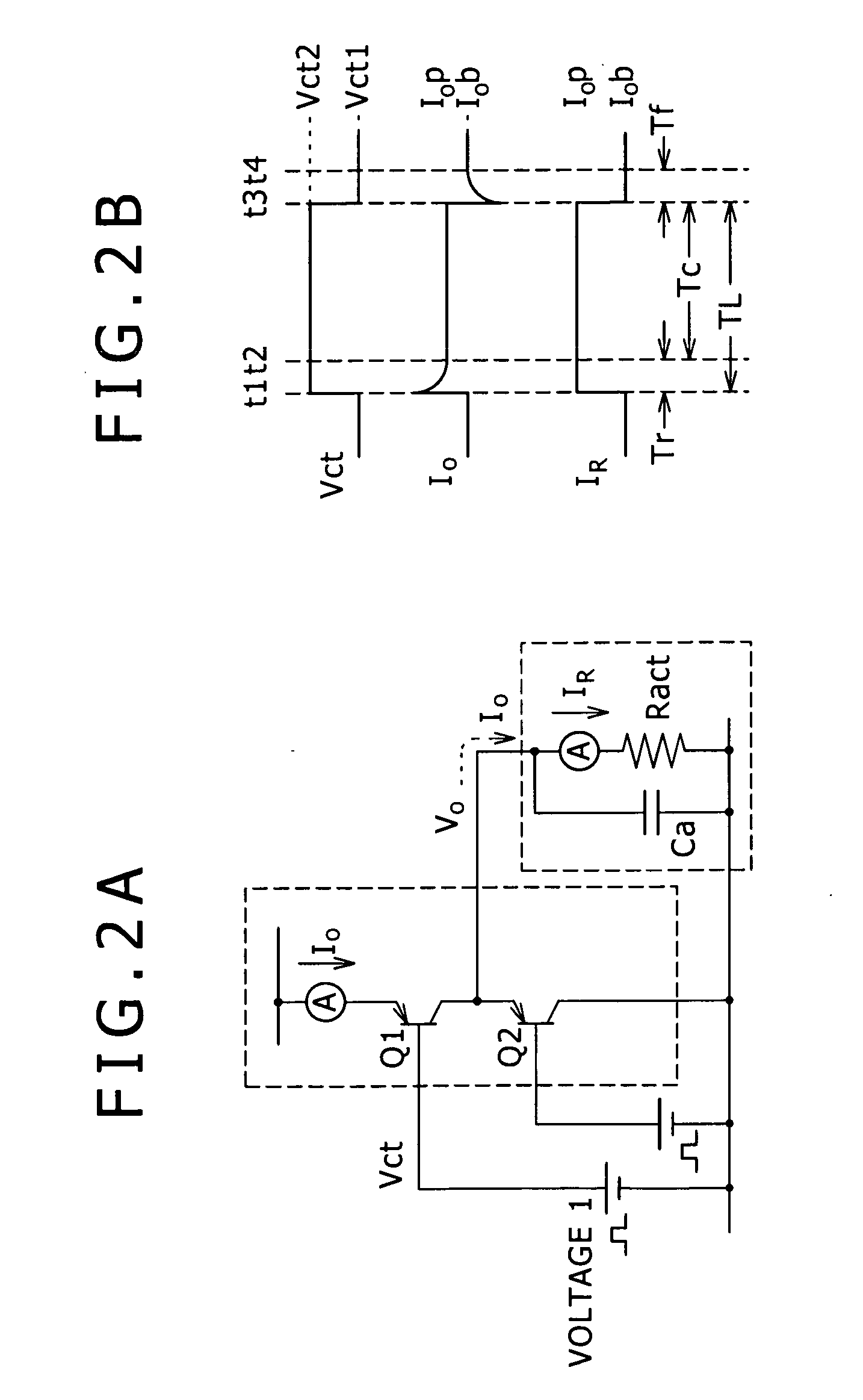
[0034]Firstly, a basic configuration of a laser driver according to an embodiment of the present invention will be described in detail with reference to FIG. 1, and FIGS. 2A and 2B.

[0035]As shown in FIG. 1, the laser driver 1 according to the embodiment of the present invention includes a light emission controlling section 10, a driving section 20, a drive current detecting section 30, a reference current detecting section 40, and a control voltage generating section 50. Also, with the configuration shown in FIG. 1, the laser driver 1 supplies a drive current I0 to a vertical cavity surface emitting laser Lm.

1.1. Configurations of ...


PUM


Abstract

Disclosed herein is a laser driver including a light emission controlling section configured to stop generation of a control voltage by a control voltage generating section, causing a given voltage corresponding to a magnitude of a reference current to be outputted to an input node of a first emitter follower to operate the first emitter follower for a first time period from start of a light emission time period, release stop of the generation of the control voltage by the control voltage generating section, causing the control voltage to be outputted to the input node of the first emitter follower to operate the first emitter follower until end of the light emission time period of the laser, and operate a second emitter follower to discharge electric charges accumulated in the laser for a second time period after the end of the light emission time period of the laser.

Description

BACKGROUND OF THE INVENTION[0001]1. Field of the Invention[0002]The present invention relates to a laser driver for causing a laser to emit a laser beam, and more particularly to a laser driver for driving a vertical cavity surface emitting laser.[0003]2. Description of the Related Art[0004]A light emission resistance of a vertical cavity surface emitting laser is about one order of magnitude larger than that of an edge emitting laser and has a resistance value of about 100Ω. In addition thereto, a parasitic capacitance of the vertical cavity surface emitting laser becomes large along with increased multiple channel. Moreover, the light emission resistance of the vertical cavity surface emitting laser changes due to a change in temperature following the light emission, and thus light emission characteristics also change.[0005]In order to cope with such a situation, for the drive for the vertical cavity surface emitting laser, the light emission characteristics are stabilized by not ...

Claims


Application Information

Patent Timeline
IPC IPC(8): H01S3/10
CPCH01S5/0428H01S5/183H01S5/06808
Inventor DAIO, KATSUHISATSUKADA, TAKAHIRO
Owner SONY CORP
Features
  • Generate Ideas
  • Intellectual Property
  • Life Sciences
  • Materials
  • Tech Scout
  • Unparalleled Data Quality
  • Higher Quality Content
  • 60% Fewer Hallucinations
Learn More