Electrical connector

a technology of electrical connectors and connectors, applied in the direction of line connector maintainance, coupling device connection, coupling device details, etc., can solve the problems of difficult to maintain reliable electrical connections, provide “break-away” functionality, and difficult to clean, so as to maintain accurate transverse positions of conductive contacts, reliable electrical connections, and easy cleaning

Active Publication Date: 2010-10-14
ITT MFG ENTERPRISES LLC
View PDF14 Cites 12 Cited by
  • Summary
  • Abstract
  • Description
  • Claims
  • Application Information

AI Technical Summary

Benefits of technology

[0015]It is known to provide collars for mechanically coupling electrical connectors with mating connectors. However, by providing a collar which can be retracted behind a forward end surface of the spacing element, and by providing means for maintaining the collar in the retracted position, the connector can be more easily maintained in a clean condition. With the collar moved forwards into the engagement position, the conductive contacts of the connector are at least partially protected from the environment.
[0023]The design of the outer body, the collar and the first and second resilient members may also be adapted such that the longitudinal force required for releasing the collar from the engagement position (when unmated) is greater than the longitudinal force required for engaging the connector with the mating connector. In this way, accidental retraction of the collar while engaging the connector with a mating connector can be avoided.
[0024]In embodiments, the outer body comprises a tubular wall, and the forward end of the outer body comprises longitudinally protruding formations, such as castellations, in the tubular wall. The longitudinally protruding formations serve as a keying arrangement for fixing the angular position of the connector with respect to the mating connector (an outer body of the mating connector being provided with corresponding formations). Additionally, the openings between the protruding formations may provide enhanced cleaning access to the conductive contacts of the connector.
[0026]In embodiments, the spacing element is formed of a resilient impermeable material, such as a resilient plastics material, for preventing the ingress of dirt into the through holes formed therein. Particularly suitable materials for the spacing element include fluorosilicone rubber materials. In connectors having a resilient spacing element, a second more rigid spacing element may be positioned in the connector behind the resilient spacing element. The second spacing element has through holes in positions corresponding to the through holes of the spacing element formed of the resilient material and serves to more accurately maintain the transverse positions of the conductive contacts.
[0027]In embodiments, forward ends of the conductive contacts are exposed in front of the end of the spacing element. In this way, the contacts can be easily cleaned with the collar in the retracted position.
[0028]The conductive contacts may be so-called “pogo contacts”. In this case, each contact comprises rearward and forward contact elements, wherein the forward contact element is longitudinally slidable relative to the rearward contact element against a spring element. In this way, a reliable electrical connection may be formed when the forward contact element is biased by the fixed contact of a mating connector.

Problems solved by technology

A significant problem in the design of an electrical connector for use with such military equipment is the need to maintain reliable electrical connections in dirty, dusty or other extreme environments.
This problem is particularly challenging where, as is typically the case, the connector is used for carrying low voltage data signals which tend to be highly sensitive and susceptible to degradation caused by environmental conditions.
The provision of “break-away” functionality, however, exacerbates the above-described problem because clamping mechanisms and the like cannot be used.

Method used


Image

  • Electrical connector
  • Electrical connector
  • Electrical connector

Examples


Embodiment Construction

1. Limited Description of the Invention

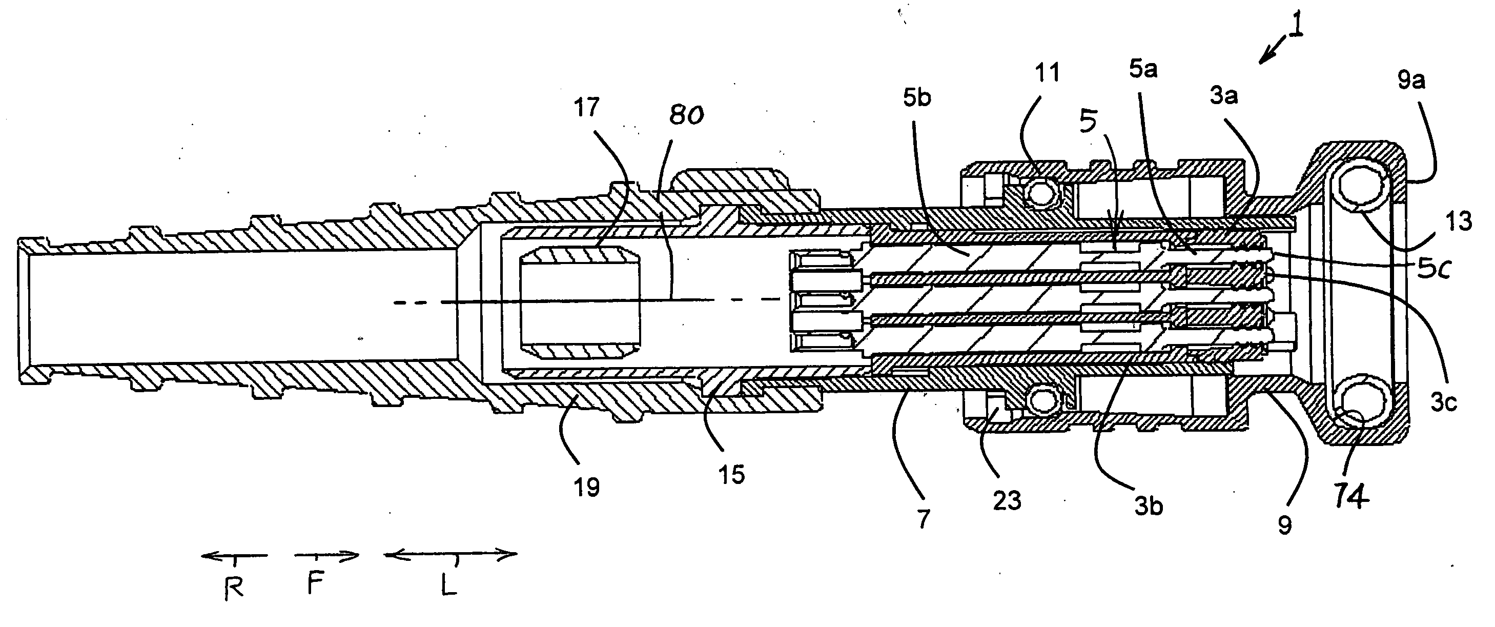
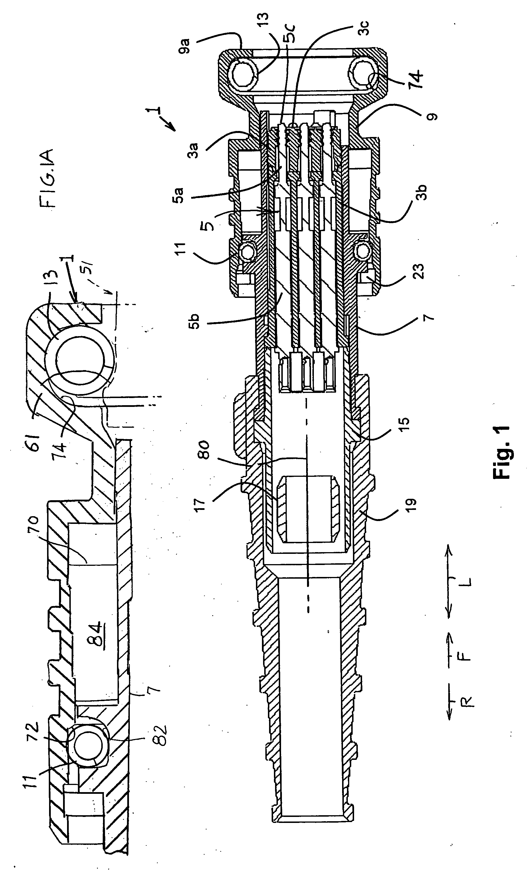
[0043]FIG. 1 shows a connector 1 which includes an outer body 7 that holds dielectric contact-holding components or spacers such as 3a and 3b which, in turn, hold electrical contacts 5. The body has an axis 80 that extends longitudinally L in forward and rearward directions F, R. The contacts have front ends 5c which engage contacts of a mating connector apparatus (51 in FIG. 5). A cable receptacle 19 at the rear of the outer body 7 and at a metal rear body 15, hold an electrical cable whose wires are connected to the electrical contacts 5.

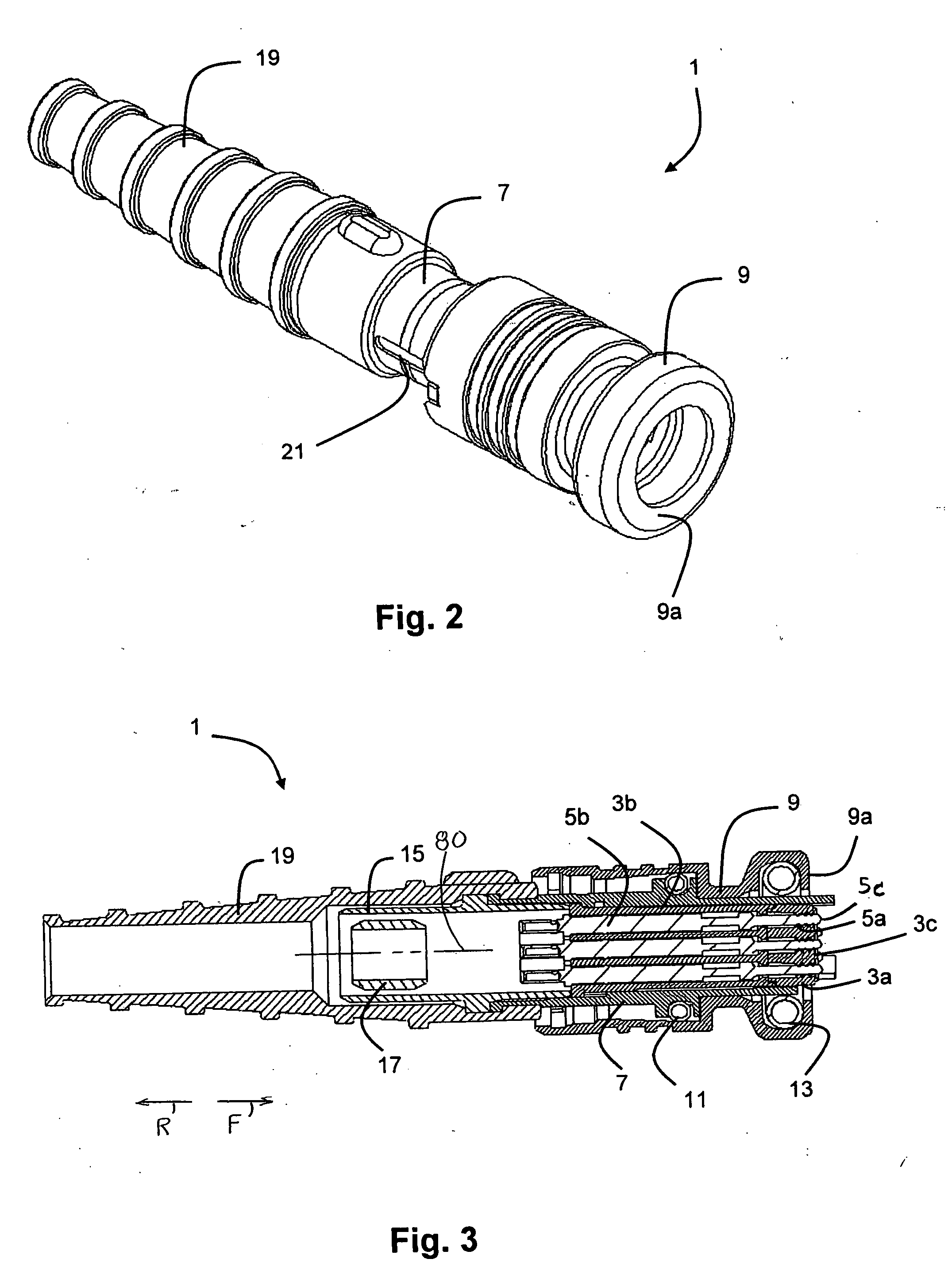
[0044]A collar 9 (FIG. 1) is slidably mounted on the front end of the outer body to slide between front and rear positions. In FIG. 1 the collar lies in a forward position wherein the collar protects the front ends of the contacts 5. In FIG. 3 the collar has been moved to its rearward position at which it exposes the front ends 5c of the contacts to facilitate cleaning them. In FIG. 3 the contact front ends 5...


PUM


Abstract

An electrical connector comprises a dielectric spacing element having elongate through holes and a forward end surface; a plurality of parallel, elongate conductive contacts arranged in respective through holes of the spacing element, the conductive contacts providing electrical connections; an outer body arranged about the spacing element and the conductive contacts, the outer body having a longitudinal position fixed relative to the dielectric spacing element and having a forward end for engagement with a mating connector; and a collar slidably mounted about the outer body. The collar has an engagement position in which a forward surface of the collar is positioned in front of the forward end of the outer body for mechanically coupling the connector with the mating connector and a retracted position in which the forward surface of the collar is positioned behind the forward end surface of the spacing element for cleaning access to the conductive contacts. The connector further comprises means, such as a resilient member, for maintaining the collar in the retracted position.

Description

CROSS-REFERENCE[0001]Applicant claims priority from Great Britain patent application GB 0906297.7 filed 14 Apr. 2009.FIELD OF THE INVENTION[0002]This invention relates to an electrical connector which is suitable for use in dirty, dusty or other extreme environments. More particularly, though not exclusively, the invention relates to such an electrical connector for use in carrying data signals and for which there is a need for in-field cleaning.BACKGROUND OF THE INVENTION[0003]There is frequently a need for electrical equipment to be used in dirty, dusty or other extreme environments. Although the provision of exposed electrical connectors in equipment intended for such environments can sometimes be effectively minimized, in many applications exposed connectors are essential for providing desired functionality.[0004]An example of electrical equipment which is designed to be suitable for use in extreme conditions is military equipment carried by infantry personnel. Such equipment in...

Claims


Application Information

Patent Timeline
Patent Type & Authority Applications(United States)
IPC IPC(8): H01R24/00
CPCH01R9/032H01R43/002H01R13/5219H01R13/5213H01R13/65912H01R13/46H01R13/502
Inventor JORDAN, PETER
Owner ITT MFG ENTERPRISES LLC
Why Eureka
Try Eureka