Intervertebral spacer

a technology of intervertebral spacer and spacer plate, which is applied in the field of surgical devices, can solve the problems of affecting affecting the stability of the spacer, etc., and achieves the effect of facilitating the introduction of spacer

Inactive Publication Date: 2010-10-14
ALFARO ARTHUR A +1
View PDF31 Cites 109 Cited by
  • Summary
  • Abstract
  • Description
  • Claims
  • Application Information

AI Technical Summary

Benefits of technology

[0011]In general, the device of the present invention may be described as a delivery system in the form of a unitary device which comprises a spacer disengagingly attached to a hollow handle. The handle facilitates the introduction of the spacer by the surgeon into the intervertebral space. The handle comprises a chamber for delivery of appropriate biologic material, and material-advancing means within the chamber for introducing the bone grafting material from the chamber into and around the spacer and the intervertebral spaces. The handle is disengageable from the spacer after serving its purpose of facilitating placement of the spacer and the discharge of the bone grafting material into the spacer and the intervertebral space.

Problems solved by technology

A difficulty with the foregoing procedure when a spacer has been pre-loaded prior to insertion, is that as the surgeon is driving the intervertebral spacer into the intervertebral space, the biologic material that had been packed into the spacer will often fall out and / or settle.
In addition, the irregularity of the surfaces of the vertebral end plates will cause cause gaps between the vertebral end plates, the biologic material and the intervertebral spacer.

Method used


Image

  • Intervertebral spacer
  • Intervertebral spacer
  • Intervertebral spacer

Examples


Embodiment Construction

[0028]The invention and various embodiments thereof will be better understood by reference to the drawings.

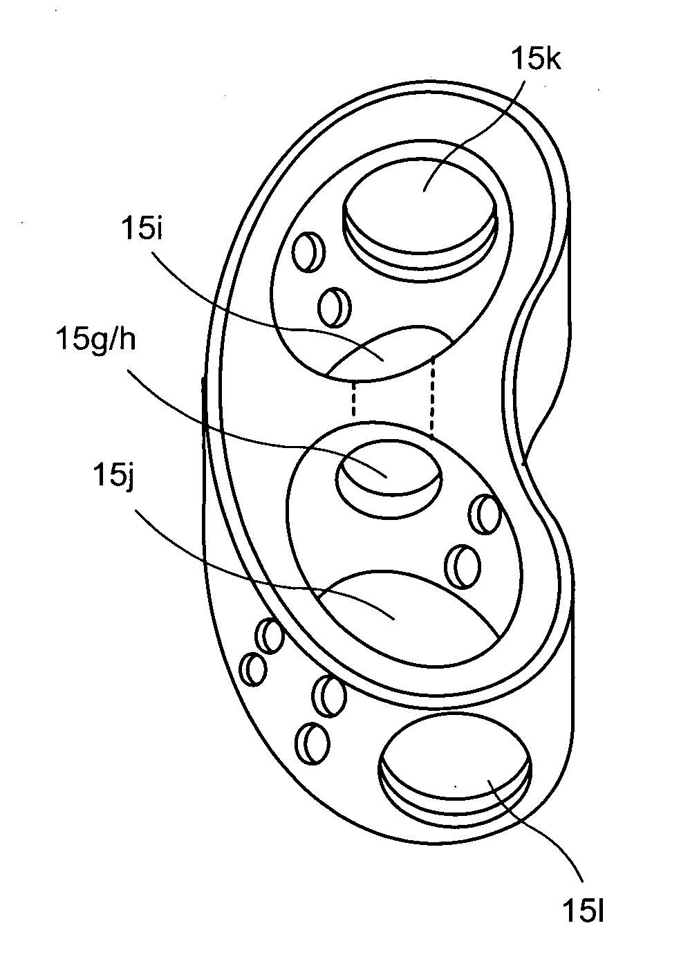
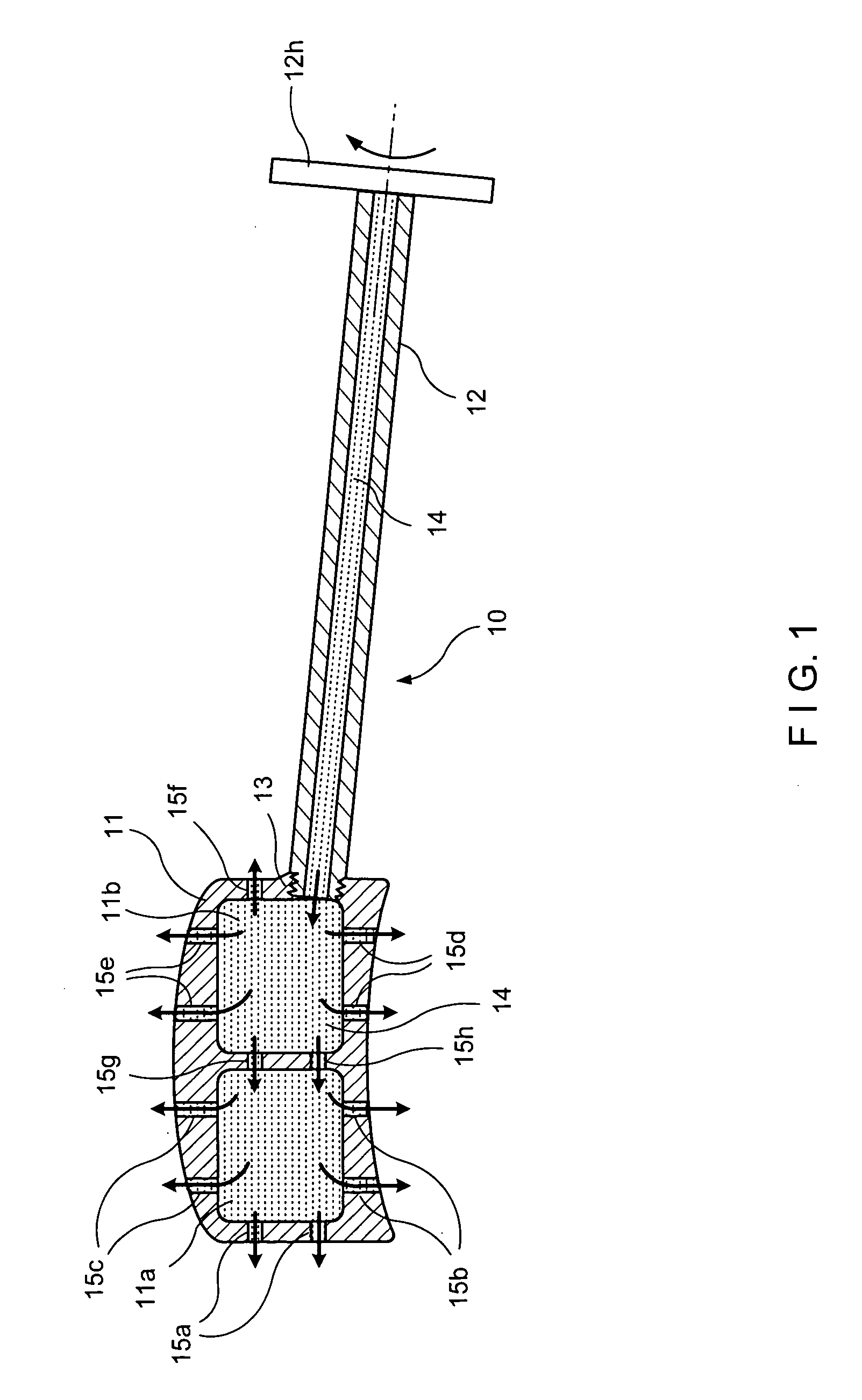
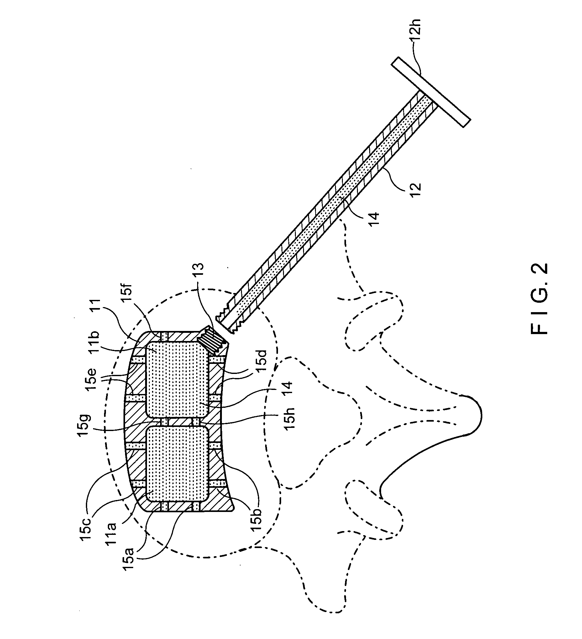
[0029]FIG. 1 shows the entire interbody grafting delivery system device 10 in a simple embodiment thereof wherein the spacer 11 is shown as part of the delivery system. FIG. 2 shows that device with the spacer 11 implanted in the anatomy of a patient. The device comprises spacer 11 which comprises open compartments 11(a) and 11(b), open at the top of the spacer and at the bottom at 15(i) and 15(j) (in FIG. 9) which are adapted to contain DBM or any other suitable biologic and communicate with the opposing vertebral surfaces to allow the biologic to flow into the space. DBM is preferred because it promotes bone growth and will fuse the surface of the spacer to the surface of the end plates more rapidly. Handle 12 is shown screwed into compartment 11(b) at 13 and is also shown to contain DBM 14 in the hollow portion of the handle and in compartments 11(a) and 11(b) and in tunnels...


PUM


Abstract

Disclosed is a delivery system for an intervertebral spacer and a bone grafting material in the form of a unitary device which comprises a spacer disengagingly attached to a hollow handle. The handle comprises a chamber and bone grafting material-advancing means within the chamber for introducing the bone grafting material from the chamber into and around the spacer and the intervertebral spaces. The handle is disengageable from the spacer after serving its purpose of facilitating placement of the spacer and the discharge of the bone grafting material into the spacer and the intervertebral space.
The intervertebral spacer implant portion is attached to the handle portion at the exit port of the chamber, the point of attachment constituting the entry port of the intervertebral spacer implant portion.
The spacer has voids therein capable of receiving the bone grafting material from the chamber, and the chamber, the spacer implant portion voids, and the intervertebral spaces are in flow communication with each other whereby bone graft material expressed from the chamber is capable of entering the intervertebral spacer implant voids and the intervertebral spaces.

Description

CROSS REFERENCE TO RELATED APPLICATIONS[0001]This application claims the benefit of U.S. Provisional Application No. 61 / 207,912 filed Feb. 18, 2009.STATEMENT REGARDING FEDERALLY SPONSORED RESEARCH OR DEVELOPMENT[0002](Not Applicable)REFERENCE TO A SEQUENCE LISTING A TABLE, OR A COMPUTER PROGRAM LISTING APPENDIX SUBMITTED ON A COMPACT DISC (SEE 37 CFR 1.52(e)(5)[0003](Not Applicable)FIELD OF THE INVENTION[0004]This invention relates to the provision of surgical devices and more particularly to surgical devices for insertion of intervertebral spacer implants and delivery of bone grafting material into intervertebral spaces in surgical procedures.BACKGROUND OF THE INVENTION[0005]It is often necessary in the correction of various spinal defects, to intervene and place exogenous devices between vertebrae in an effort to fuse adjacent vertebrae to each other. One particular modality is to introduce a solid material into the vertebral space following a surgical discectomy The solid materia...

Claims


Application Information

Patent Timeline
Patent Type & Authority Applications(United States)
IPC IPC(8): A61F2/44A61B17/58
CPCA61F2/4465A61F2/4601A61F2/4611A61F2002/2817A61F2002/2835A61F2230/0015A61F2002/30785A61F2002/30787A61F2002/4627A61F2002/4629A61F2002/30133
Inventor ALFARO, ARTHUR A.BUREL, MARC
Owner ALFARO ARTHUR A
Why Eureka
Try Eureka