Angular velocity sensor

a technology of angular velocity and sensor, which is applied in the direction of acceleration measurement using interia force, turn-sensitive devices, instruments, etc., can solve the problems of large difference in vibration generation among the mass portions, increase of noise, increase of the influence of vibration leakage, etc., and achieve the effect of stabilizing the resonance sta

Active Publication Date: 2010-10-21
MURATA MFG CO LTD
View PDF12 Cites 54 Cited by
  • Summary
  • Abstract
  • Description
  • Claims
  • Application Information

AI Technical Summary

Benefits of technology

[0038]Since the monitoring elements arranged to monitor displacements of the driven mass portions in directions of vibrations thereof are disposed around the driven mass portions, the amplitudes and the phases of the vibrations in the driven mass portions can be detected using the monitoring elements. Therefore, an oscillation circuit arranged to drive the driven mass portions to vibrate can utilize, as a reference signal, output signals of the monitoring elements. Thus, the resonance state can be stabilized. Further, an angular velocity detection circuit can also utilize, as a reference signal, the output signals of the monitoring elements. Thus, synchronous detection can be precisely performed depending on the vibration states of the driven mass portions.

Problems solved by technology

Therefore, if manufacturing variations occur in the mass portions and the springs, a large difference in vibrations is generated among the mass portions when the mass portions are vibrated in a resonance state.
This leads to a tendency for the vibrations of the mass portions to leak to the substrate, thus causing problems, such as fluctuations of an offset and an increase of noise, as the temperature changes.
Therefore, coupling occurs between the vibration having been driven and the vibration to be detected, which increases the influence of a leak of the vibrations.
However, the disclosed angular velocity sensor is not suitable for specifications that are demanded in some practical applications because it does not detect the angular velocities about the two axes (i.e., the X-axis and the Y-axis) parallel to the substrate.
Thus, because the spring and the ring-shaped vibrator are both used in driving and detecting vibrations, coupling is likely to occur between the driven vibration and the detected vibration.
However, because the width of the ring-shaped vibrator is relatively small, change in the capacitance between the ring-shaped vibrator and the detection electrode is also relatively small and the detection sensitivity tends to be reduced.
This causes another problem in that the resonance frequency of the ring-shaped vibrator is increased and the detection sensitivity of the angular velocity is reduced.

Method used


Image

  • Angular velocity sensor
  • Angular velocity sensor
  • Angular velocity sensor

Examples


Embodiment Construction

[0060]Angular velocity sensors according to preferred embodiments of the present invention will be described in detail below with reference to the accompanying drawings.

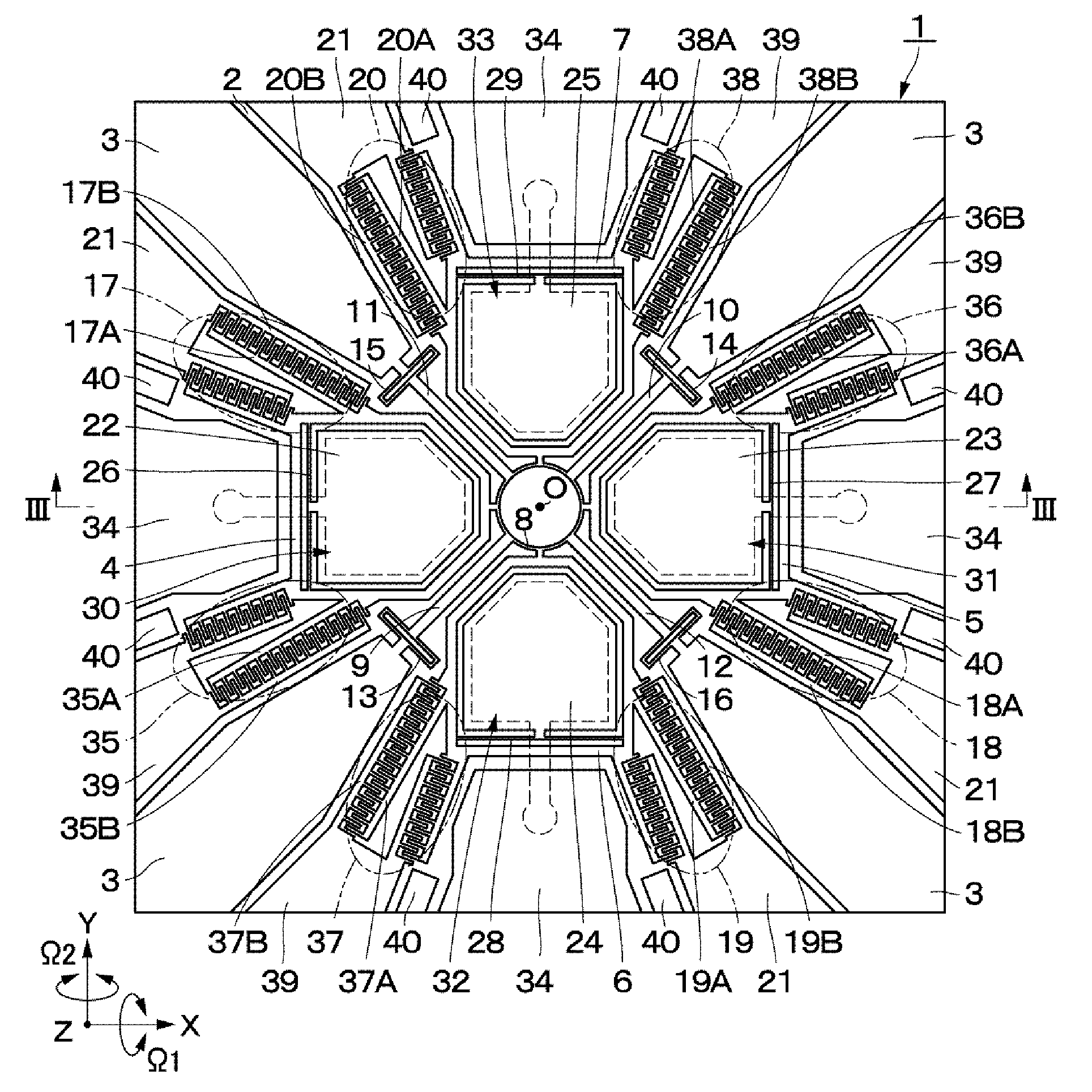
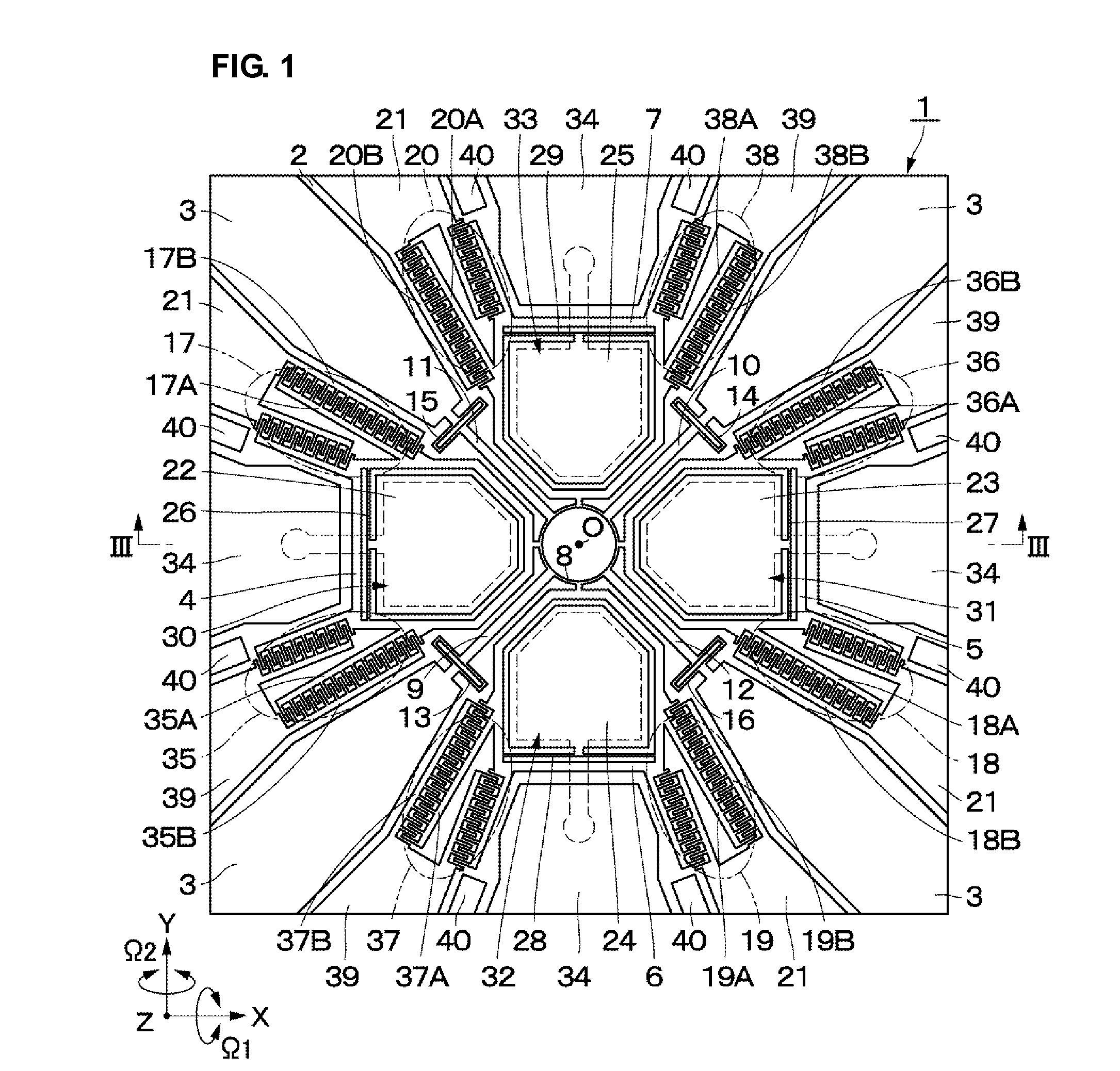
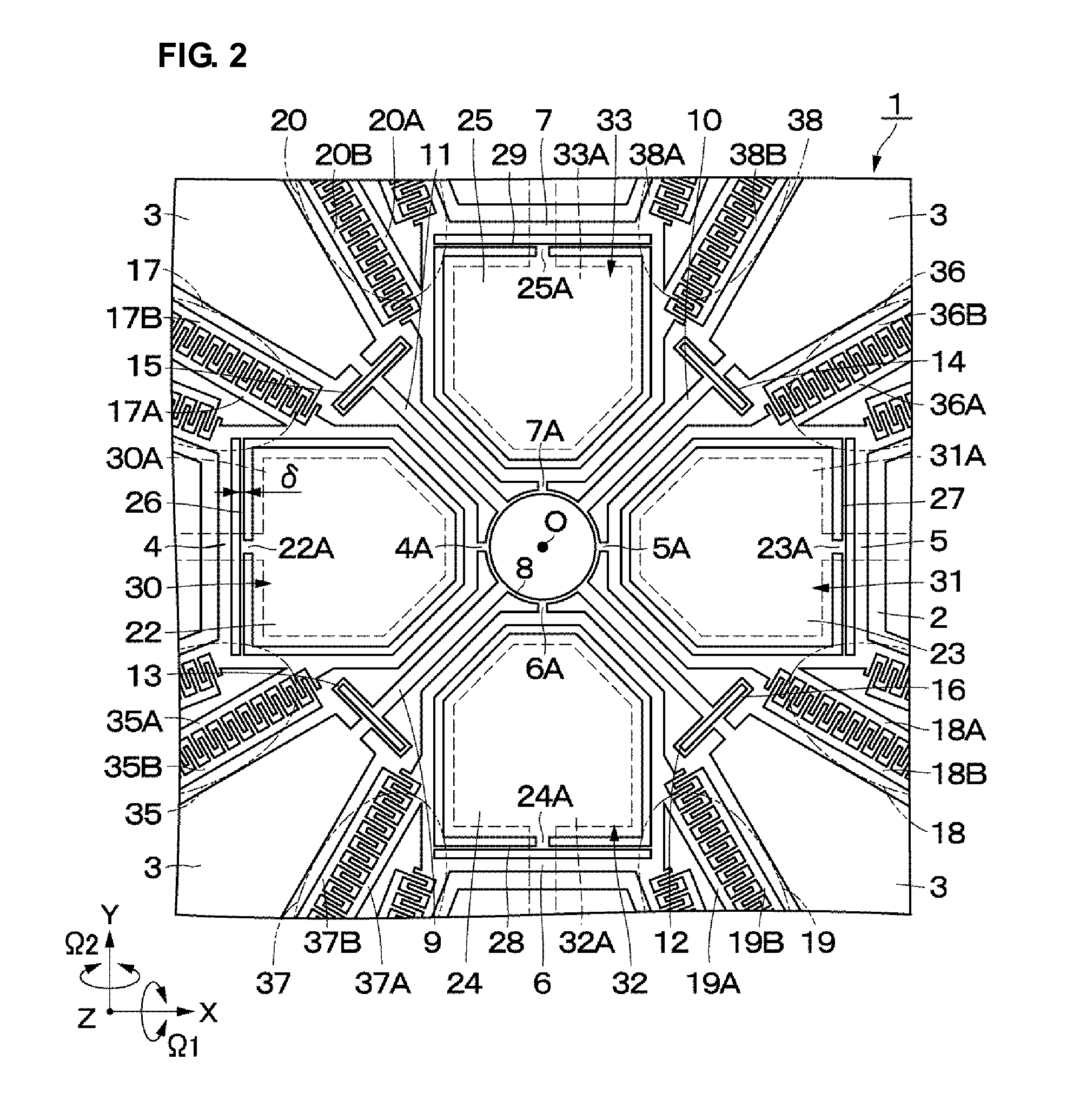
[0061]FIGS. 1 to 6 illustrate an angular velocity sensor 1 according to a first preferred embodiment of the present invention. As illustrated in FIGS. 1 to 6, the angular velocity sensor 1 includes a base plate 2, driven mass portions 4 to 7, a coupling beam 8, connecting portions 9 to 12, driven beams 13 to 16, vibration generating portions 17 to 20, detecting mass portions 22 to 25, detecting beams 26 to 29, displacement detecting portions 30 to 33, and vibration monitoring portions 35 to 38.

[0062]A base plate 2 defines a base portion of the angular velocity sensor 1. The base plate 2 is preferably a rectangular or substantially rectangular flat plate made of, e.g., a glass material. The base plate 2 extends horizontally in, e.g., X- and Y-axis directions among three X-, Y- and Z-axis directions that are perpendicu...


PUM


Abstract

In an angular velocity sensor, driven mass portions are disposed on a surface of a base plate at point-symmetrical locations with respect to a central point O. The driven mass portions are connected to a coupling beam to be interconnected. The coupling beam is flexibly supported through connecting portions and driven beam. Detecting mass portions are disposed inside the driven mass portions, and the detecting mass portions are supported by detecting beams to be displaceable in the Z-axis direction. Two adjacent ones of the driven mass portions in the circumferential direction are vibrated by vibration generation portions in opposite phases to each other. When angular velocities are exerted in such a state, the detecting mass portions are caused to displace and vibrate in the direction of thickness of the base plate. Displacement detecting portions detect displacements of the detecting mass portions in the direction of the thickness.

Description

BACKGROUND OF THE INVENTION[0001]1. Field of the Invention[0002]The present invention relates to an angular velocity sensor that is used to detect angular velocities in two-axis directions, for example.[0003]2. Description of the Related Art[0004]In general, a known angular velocity sensor includes a plurality of mass portions provided on a substrate. Japanese Unexamined Patent Application Publication No. 11-183179 and Japanese Unexamined Patent Application Publication No. 2006-138855 disclose an arrangement in which four mass portions are provided on the substrate along a circumference thereof and two adjacent mass portions in the circumferential direction are vibrated in directions opposite to each other. In such an arrangement, when an angular velocity about each of two axes is exerted on the substrate parallel to the surface of the substrate in a state in which the four mass portions are vibrated, the four mass portions are displaced in the vertical direction (i.e., the directio...

Claims


Application Information

Patent Timeline
Patent Type & Authority Applications(United States)
IPC IPC(8): G01C19/56G01C19/5621G01C19/5628
CPCG01C19/5719G01C19/5712
Inventor TAMURA, MASAYAMOCHIDA, YOICHI
Owner MURATA MFG CO LTD
Why Eureka
Try Eureka