Swing Wrench

a wrench and wrench technology, applied in the field of hand tools, can solve the problems of time-consuming, tedious, and inability to achieve the combination of traditional and one-way driving features at the same tim

Inactive Publication Date: 2010-10-21
HUANG PING WEN
View PDF10 Cites 13 Cited by
  • Summary
  • Abstract
  • Description
  • Claims
  • Application Information

AI Technical Summary

Benefits of technology

[0007]An objective of the invention is to provide a swing wrench that can restricts the swinging state of the wrench so that it has both traditional and one-way driving features.

Problems solved by technology

This is very tedious and time-consuming.
However, the above-mentioned wrench structure is designed to only provide the single function of rotating the bolt in one way, much like the ratchet wrench.
It cannot achieve the both traditional and one-way driving features at the same time.

Method used


Image

  • Swing Wrench
  • Swing Wrench
  • Swing Wrench

Examples


first embodiment

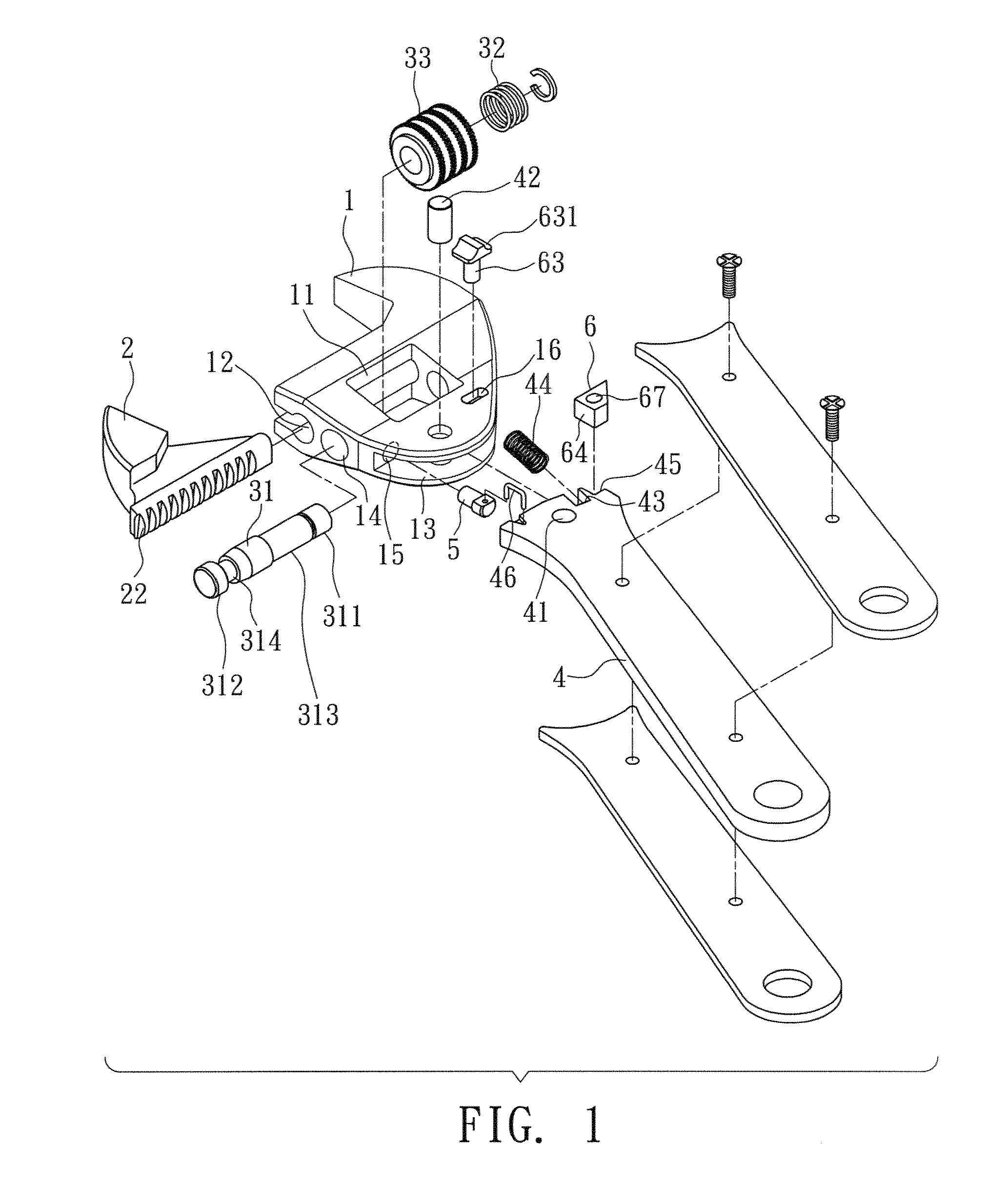
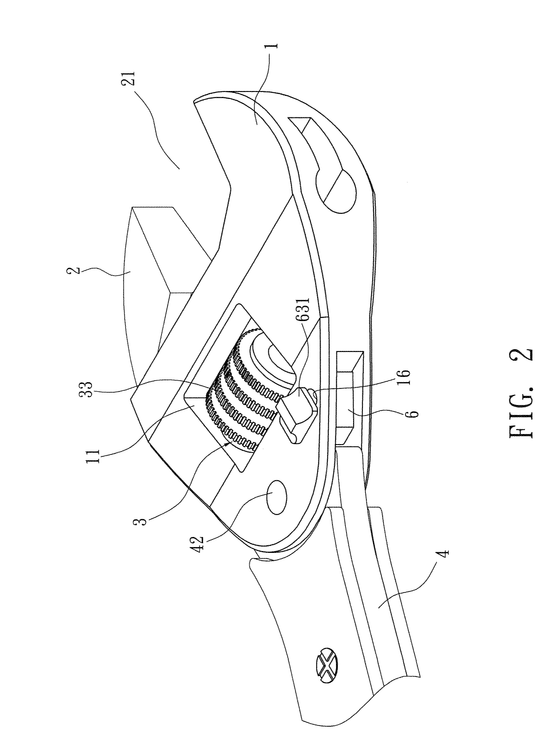
[0026]Please refer to FIGS. 1 to 4 for the invention. This embodiment provides a swing wrench comprising a fixing jaw 1, a moving jaw 2, an acting set 3, a handle 4, a blocking pin 5, and a fixing element 6.

[0027]The fixing jaw 1 has an accommodating tank 11. A sliding track 12 is provided above and in communication with the accommodating tank 11. A pivotal groove 13 is formed below the accommodating tank 11, connecting to the exterior. One side of the accommodating tank 11 is formed horizontally with a through hole 14. A connecting hole 15 is formed inside the through hole 14 in the radial direction. The connecting hole 15 further connects with the pivotal groove 13.

[0028]The moving jaw 2 is disposed in the sliding track 12 to move sideways therein. The moving jaw 2 and the fixing jaw 1 form a holding zone 21 with a variable gap. The bottom of the moving jaw 2 has a tooth part 22.

[0029]The acting set 3 is disposed in the accommodating tank 11 of the fixing jaw 1. It includes a shaf...

third embodiment

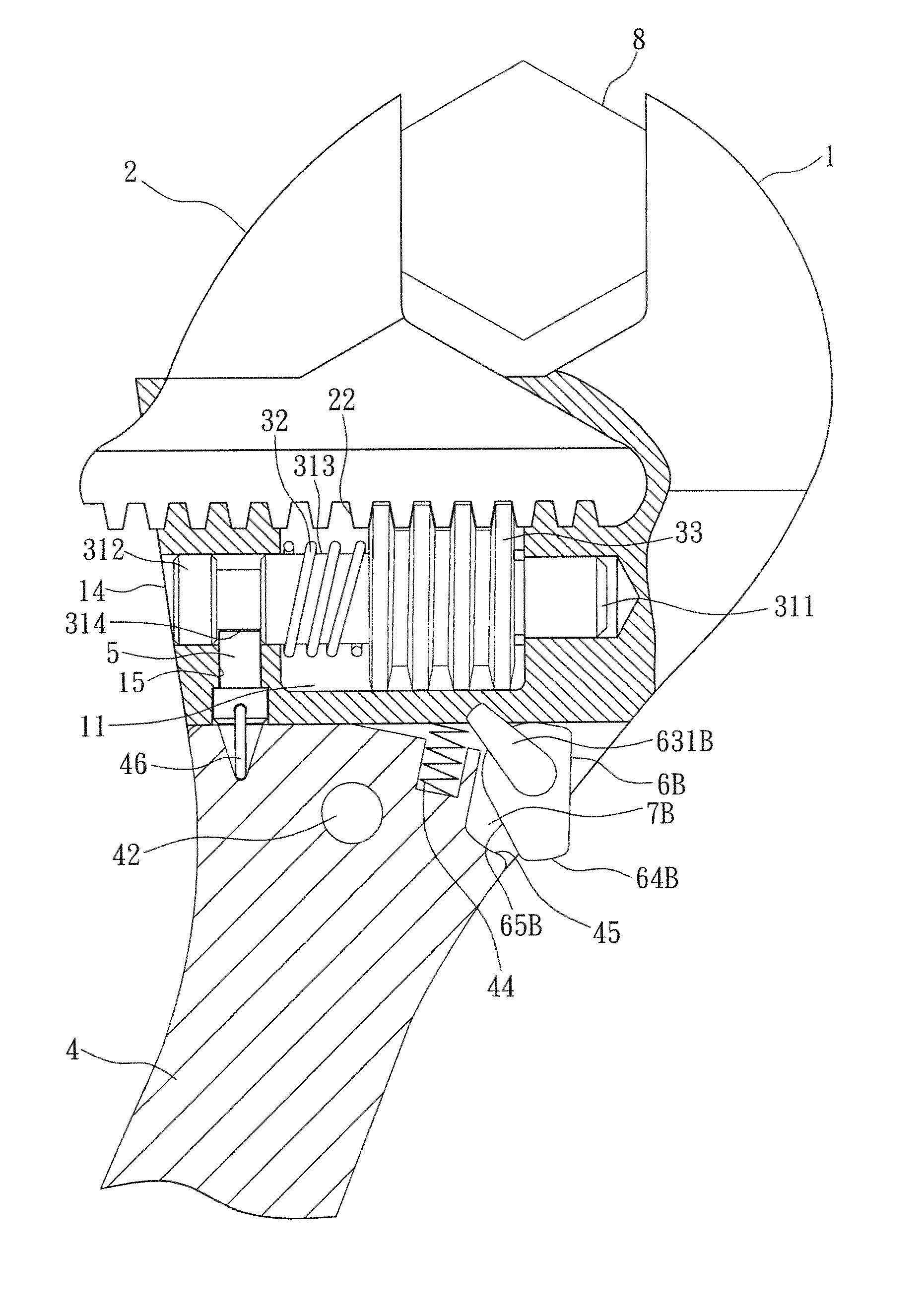
[0041]FIG. 12 shows the invention. It differs from the above-mentioned two embodiments in that the limiting section 64B and the moving section 65B are formed around the fixing element 6B. One end of the pin 63B goes from the outer side of the pivotal groove 13 into the concave part 61B of the fixing element 6B, thereby connecting to the fixing element 6B. The other end of the pin 63B bends outward to form an exerting part 631B. When the user applies a force on the exerting part 631B, it brings the fixing element 6B into rotation simultaneously. The fixing element 6B can selectively use its limiting section 64B or the moving section 65B to face the fixing part 45 of the handle 4.

[0042]As shown in FIG. 13, when the user rotates the exerting part 631B so that the limiting section 64B faces the fixing part 45 of the handle 4, they are engaged to prevent the handle 4 from swinging. When the user rotates the exerting part 631B so that the limiting part 64B of the fixing element 6B moves a...


PUM


Abstract

A swing wrench includes a fixing jaw, a moving jaw, an acting set, and a handle pivotally fixed to the bottom of the fixing jaw. A fixing element is disposed between the bottom of the fixing jaw and the front end of the handle. A limiting section is disposed around the fixing element. A fixing part is formed at the front end of the handle, opposite to the fixing element. The limiting section of the fixing element can engage or move away from the fixing part of the handle. When the limiting section is away from the fixing part, a swing space is formed in between for the handle to pivotally swing with respect to the fixing jaw.

Description

BACKGROUND OF THE INVENTION[0001]1. Field of Invention[0002]The invention relates to a hand tool and, in particular, to a swing wrench that has both traditional and one-way driving features.[0003]2. Related Art[0004]Using a normal wrench to lock or unlock a polygonal bolt, the user usually has to repeatedly remove and engage the wrench on the bolt. This is very tedious and time-consuming. In view of this, many improved wrenches have been invented to solve the problem. Consequently, the wrench can be used like a ratchet wrench; the user can conveniently swing the wrench reciprocally to lock or unlock the bolt.[0005]The improved structure of a moveable wrench disclosed in ROC Pat. No. M300,594 is also proposed by the present inventor. It mainly includes a fixing jaw, a moving jaw, a handle, a shaft, and a blocking pin. The joint between the front end of the handle and the fixing jaw is used as the pivot point. When the user swings the handle back and forth, the handle drives the block...

Claims


Application Information

Patent Timeline
Patent Type & Authority Applications(United States)
IPC IPC(8): B25B13/20
CPCB25B13/46B25B13/14
Inventor HUANG, PING WEN
Owner HUANG PING WEN
Why Eureka
Try Eureka