

Watercraft
- Summary
- Abstract
- Description
- Claims
- Application Information
AI Technical Summary
Benefits of technology
Problems solved by technology
Method used
Image

Examples
first embodiment
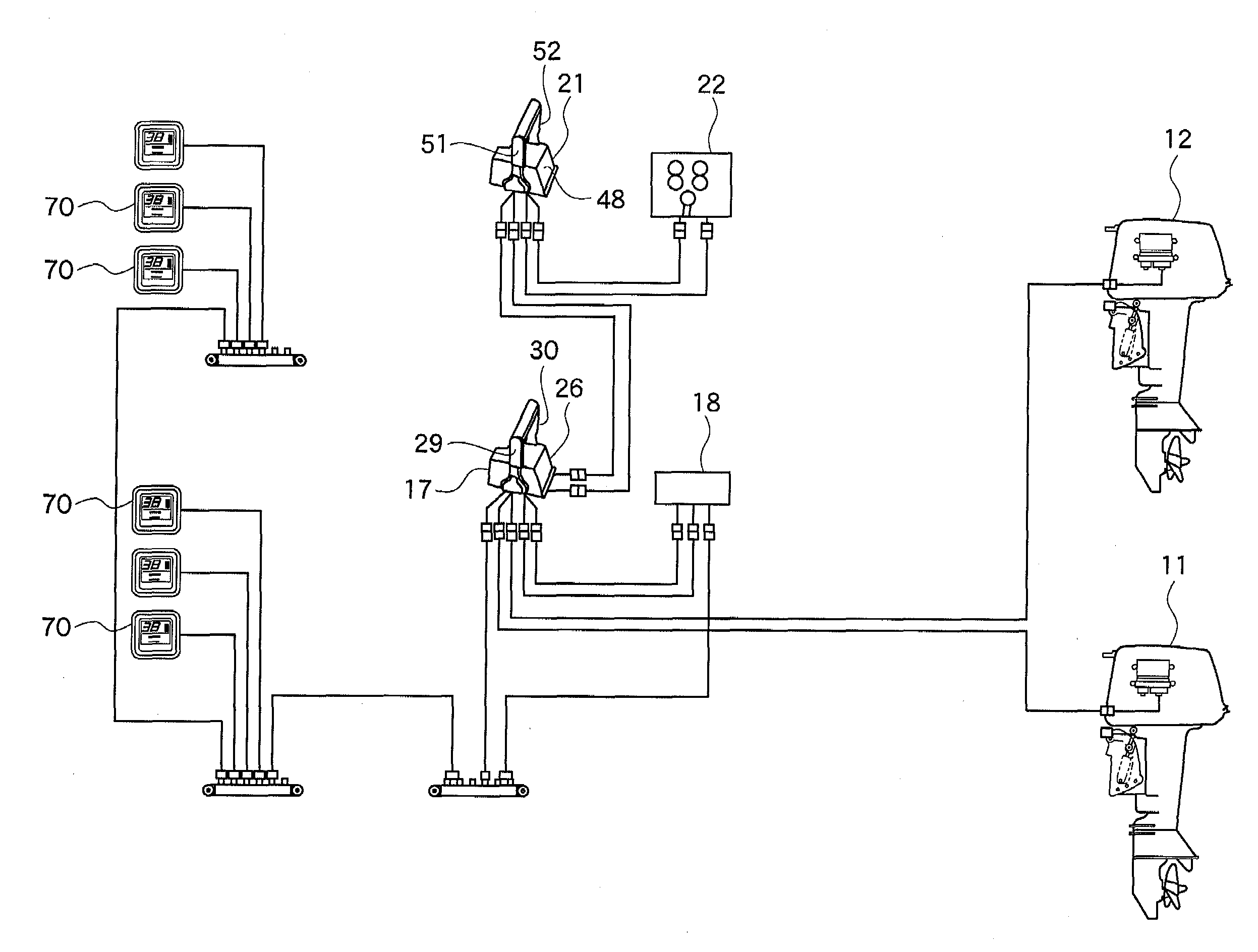
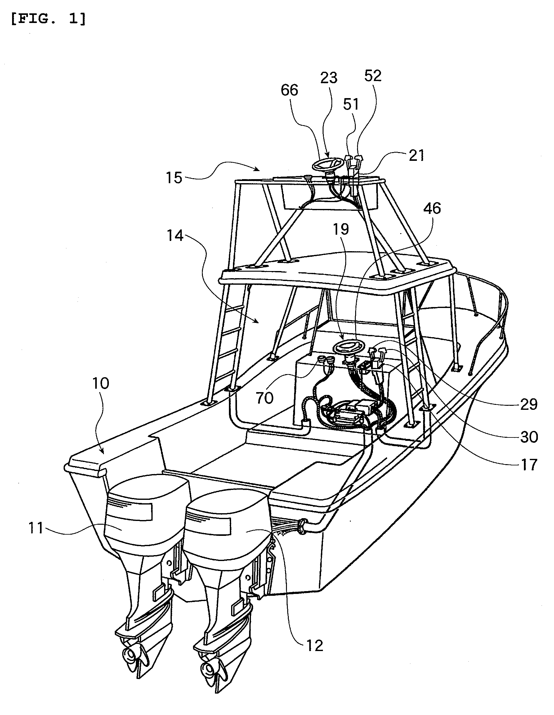
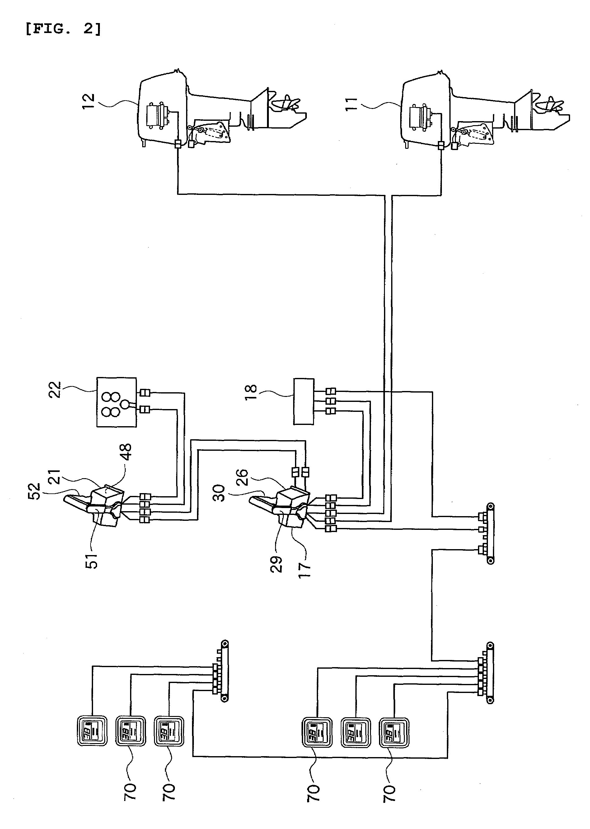
[0032]a watercraft 10 is illustrated in FIGS. 1 through 4. With initial reference to FIGS. 1 and 2, the watercraft 10 includes two outboard motors 11 and 12 (or “watercraft propulsion units”) whose power supply systems can be independent from one another. The outboard motors 11, 12 can be provided on a stern of a hull 10, and two cockpits including a main station 14 and a substation 15 can be provided on the hull 10. A main station side remote controller 17, a key switch device 18, and a steering wheel unit 19 are disposed in the main station 14. A substation side remote controller 21, a key switch device 22, and a steering wheel unit 23 can be disposed in the substation 15.
[0033]As shown in FIG. 3, in the main station side remote controller 17, a main station remote controller side ECU 27 for left unit as a “controlling unit” for the outboard motor 11 on the left side and a main station remote controller side ECU 28 for right unit as a “controlling unit” for the outboard motor 12 o...
second embodiment
[0067]FIG. 5 shows a schematic illustration of the connection between remote controllers and outboard motors of a watercraft of a
[0068]The watercraft can include three outboard motors 71, 72, and 73, and is configured so that these outboard motors 71, 72 and 73 can be operated by a main station side remote controller 76 and a substation side remote controller 77 respectively provided on a main station 74 and a substation 75.
[0069]A pair of remote controller levers 78 and 79 can be provided on the main station side remote controller 76, while three main station remote controller side ECUs 81, 82 and 83 corresponding to the three outboard motors 71, 72 and 73 can be provided through a direct connection to the respective outboard motors. A position sensor of the remote controller lever 78 can be operatively connected to the main station remote controller side ECUs 81 and 82 and also a position sensor of the remote controller lever 79 can be connected to the main station remote controll...
third embodiment
[0082]In each of the remote controller side ECUs 94 and 95, a lever selection control section is provided so that the outboard motors 11 and / or 12 with the respective remote controller levers 91 and / or 92 are selected according to these lever selecting switches 96 and correspondence between the remote controller levers 91 and 92 and the respective remote controller side ECUs 94 and 95 can be controlled. In the third embodiment, each of the remote controller side ECUs 94 and 95 of the remote controller 90 disposed in the main station 14 includes the lever selection control section, and the remote controller side ECUs 94 and 95 disposed in the main station 14 are connected by the communication line between ECUs g.
[0083]The configuration can be the same as in the first embodiment, except the description above.
[0084]The lever selection control section included in the remote controller side ECUs 94 and 95 of such a watercraft is configured so that switching processes shown in FIG. 7 can ...
PUM
 Abstract
Description
Claims
Application Information