Robot deployed weapon system and safing method

a robot and weapon technology, applied in the field of robots, weapon control, and remotely controlled mobile robots, can solve the problem that the system has not been deployed by the military

Active Publication Date: 2010-10-21
FOSTER-MILLER
View PDF22 Cites 33 Cited by
  • Summary
  • Abstract
  • Description
  • Claims
  • Application Information

AI Technical Summary

Benefits of technology

[0004]It is therefore an object of this invention to provide

Problems solved by technology

To date, such a system has not been deployed by t

Method used


Image

  • Robot deployed weapon system and safing method
  • Robot deployed weapon system and safing method
  • Robot deployed weapon system and safing method

Examples


Embodiment Construction

[0030]Aside from the preferred embodiment or embodiments disclosed below, this invention is capable of other embodiments and of being practiced or being carried out in various ways. Thus, it is to be understood that the invention is not limited in its application to the details of construction and the arrangements of components set forth in the following description or illustrated in the drawings. If only one embodiment is described herein, the claims hereof are not to be limited to that embodiment. Moreover, the claims hereof are not to be read restrictively unless there is clear and convincing evidence manifesting a certain exclusion, restriction, or disclaimer.

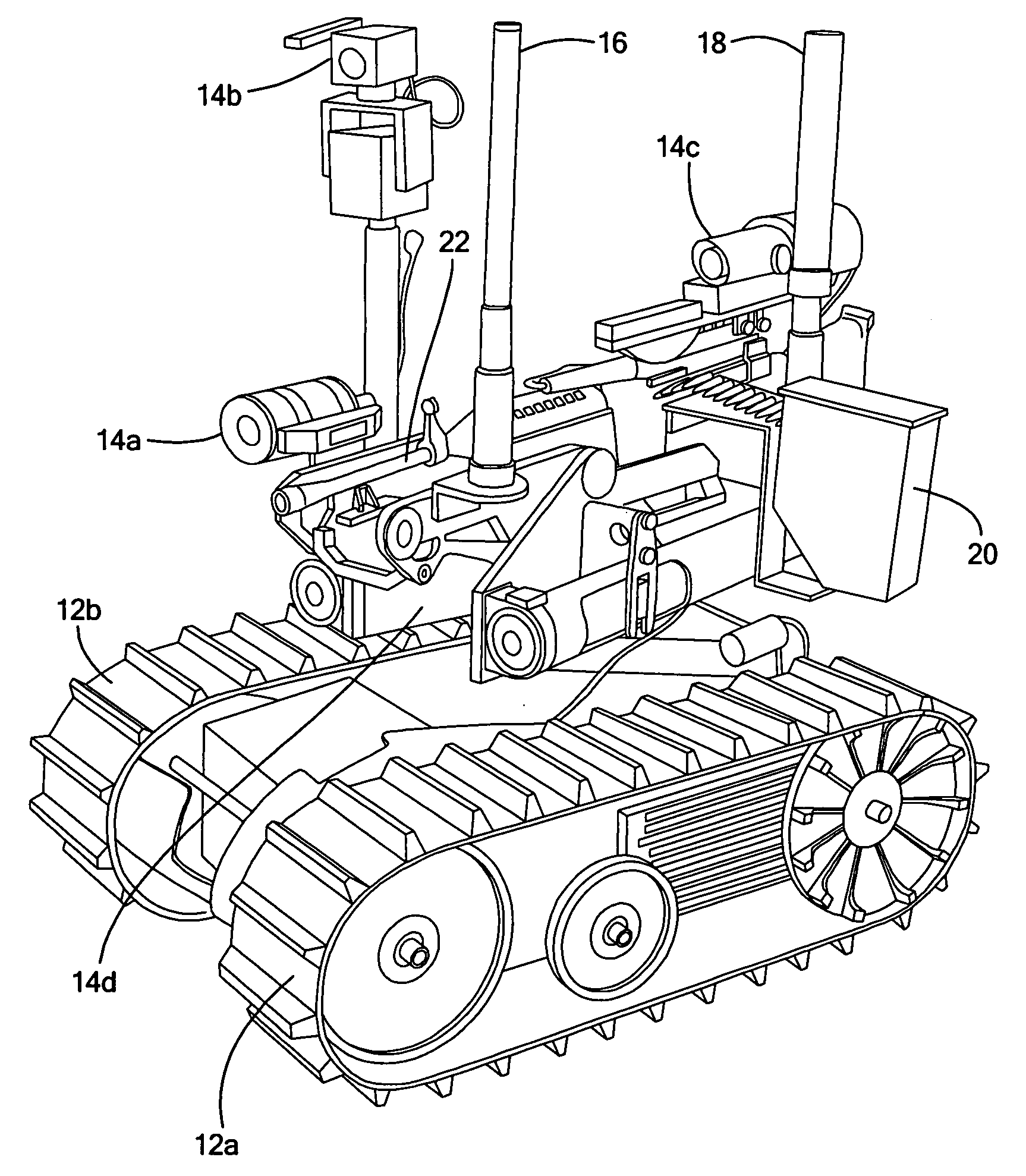
[0031]FIG. 1 shows an example of a robot 10 in accordance with this invention. The basic robot platform is preferably based on Foster-Miller, Inc.'s (Waltham, Mass.) “Talon” robot and includes motor driven tracks 12a and 12b. Robot 10 also includes cameras 14a, 14b, 14c, and 14d; video antenna 18, data antenna 16, ammunitio...


PUM


Abstract

This subject invention features a robot deployed weapon system. A remotely controlled mobile robot has a weapon mounted to the robot. There is a firing circuit for the weapon and a weapon interrupt module on board the robot. An operator control unit is for remotely operating the robot and the weapon. The operating control unit preferably includes a stop switch. Also, a separate operator module is in communication with the weapon interrupt module. Preferably, the operator module includes a kill switch. There are two communication links. The first communication link is between the operator control unit and the robot. This communication link is configured to safe the weapon if the stop switch is activated and/or the first communication link degrades. The second communication link is between the operator module and the weapon interrupt module. The communication link is configured to safe the weapon if the kill switch is activated and/or the second communication link degrades.

Description

FIELD OF THE INVENTION[0001]This subject invention relates to robotics, weapon control, and remotely controlled mobile robots equipped with weapons.BACKGROUND OF THE INVENTION[0002]The notion of a mobile remotely controlled robot with a weapon mounted thereto is intriguing. The robot could be maneuvered into a hostile situation and the weapon fired by an operator positioned out of harm's way.[0003]To date, such a system has not been deployed by the military primarily because of safety concerns. That is, steps must be taken to ensure that the weapon fires only when the operator so intends, stops firing when desired, and does not fire in the case of a malfunction with the robot, the weapon, and / or any of the controlling electronics or software.SUMMARY OF THE INVENTION[0004]It is therefore an object of this invention to provide a mobile remotely controlled weapon platform which is safe.[0005]It is a further object of this invention to provide a robot deployed weapon system wherein the ...

Claims


Application Information

Patent Timeline
IPC IPC(8): F41A17/00
CPCF41A23/34F41H7/005F42D5/04
Inventor MORIN, GARY R.DEGUIRE, DANIEL R.BRUCK, KURTCHUNG, JAMESPLATT, DAVID
Owner FOSTER-MILLER
Why Eureka
Try Eureka