Dual level pressurization control based on fuel flow to one or more gas turbine engine secondary fuel loads

a gas turbine engine and secondary fuel technology, applied in the direction of machines/engines, flexible member pumps, positive displacement liquid engines, etc., can solve the problems of excessive fuel system heat, difficult priority flow scheduling, and undesirable results

Active Publication Date: 2010-10-21
HONEYWELL INT INC
View PDF6 Cites 27 Cited by
  • Summary
  • Abstract
  • Description
  • Claims
  • Application Information

AI Technical Summary

Benefits of technology

[0006]In one embodiment, and by way of example only, a fluid pressurization control system includes a secondary flow control valve and a pressurizing valve. The secondary flow control valve includes an inlet port and an outlet port. The inlet port is adapted to receive fuel discharged from a fuel pump. The secondary flow control valve is movable between a closed position, in which the inlet port is fluidly isolated from the outlet port, and an open position, in which the inlet port is in fluid communication with the outlet port. The pressurizing valve is adapted to receive fuel discharged from the fuel pump at a pump discharge backpressure, is in fluid communication with at least the secondary flow control valve outlet port, and includes a control pressure select piston and a pressure control piston. The control pressure select piston is responsive, at least in part, to fuel pressure at the secondary flow control valve outlet port to move between a first position and a second position. The pressure control piston is controllably movable to maintain the pump discharge backpressure above a first value when the control pressure select piston is in the first position, and above a second value when the control pressure select piston is in the second position.
[0007]In another exemplary embodiment, a fuel supply and control system includes a fuel pump, a metering valve, a secondary flow control valve, and a pressurizing valve. The fuel pump is adapted to receive fuel at a pump inlet pressure and supply the fuel at a pump discharge backpressure. The metering valve is in fluid communication with the fuel pump to receive at least a first portion of the fuel supplied therefrom. The metering valve is configured to control fuel flow to one or more primary fuel loads. The secondary flow control valve includes an inlet port and an outlet port. The inlet port is in fluid communication with the fuel pump to receive at least a second portion of the fuel supplied therefrom. The secondary flow control valve

Problems solved by technology

This solution, however, may exhibit certain undesirable drawbacks.
For example, this solution can make the scheduling of priority flow difficult du

Method used


Image

  • Dual level pressurization control based on fuel flow to one or more gas turbine engine secondary fuel loads
  • Dual level pressurization control based on fuel flow to one or more gas turbine engine secondary fuel loads
  • Dual level pressurization control based on fuel flow to one or more gas turbine engine secondary fuel loads

Examples


Embodiment Construction

[0014]The following detailed description is merely exemplary in nature and is not intended to limit the invention or the application and uses of the invention. Furthermore, there is no intention to be bound by any theory presented in the preceding background or the following detailed description. In this regard, although an embodiment of the invention is described as being implemented in an aircraft and for a gas turbine engine, it will be appreciated that the invention may be implemented in numerous and varied end-use environments where fuel flow to primary and secondary fuel loads is controlled.

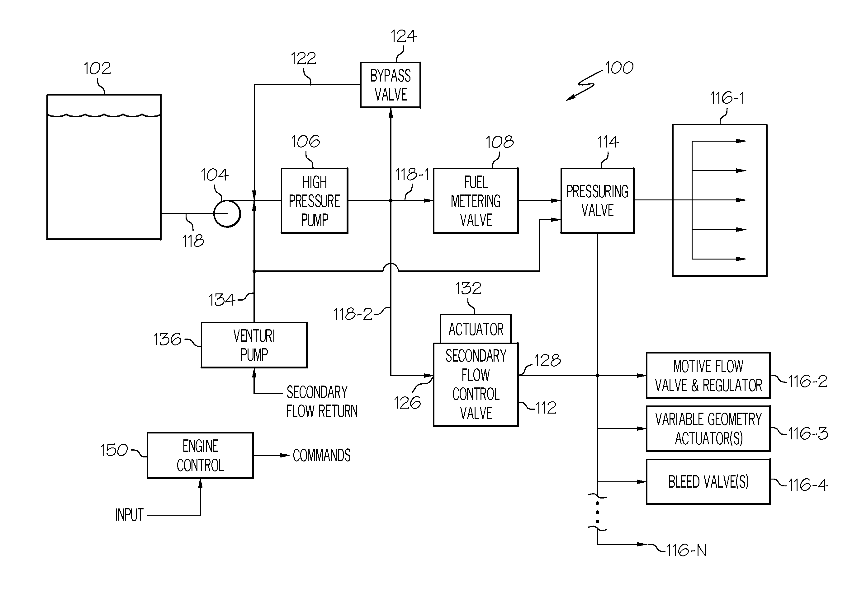
[0015]Turning now to FIG. 1, a simplified schematic diagram of one embodiment of a fuel delivery and control system for a gas turbine engine, such as a turbofan jet aircraft engine, is depicted. The system 100 includes a fuel source 102, one or more pumps 104, 106, a fuel metering valve 108, a secondary flow control valve 112, a pressurizing valve 114, and an engine control 150. The fuel so...


PUM


Abstract

A system and method provide dual level pressurization control of a fuel supply system based on whether fuel is being supplied to one or more secondary fuel loads. Fuel pump discharge backpressure is maintained above either a first minimum pressure value or a lower second minimum pressure value by determining whether fuel is being supplied to one or more secondary fuel loads. The fuel pump discharge pressure is maintained above the first minimum pressure value if it is determined that fuel is being supplied to the one or more secondary loads. The fuel pump discharge backpressure is maintained above the lower second minimum pressure value if it is determined that fuel is not being supplied to the one or more secondary loads.

Description

TECHNICAL FIELD[0001]The present invention generally relates to gas turbine engine fuel pressurization control and, more particularly, to a system and method for implementing dual level pressurization control based on whether fuel is being supplied to one or more secondary fuel loads.BACKGROUND[0002]Typical gas turbine engine fuel supply systems include a fuel source, such as a fuel tank, and one or more pumps. The one or more pumps draw fuel from the fuel tank and deliver pressurized fuel to one or more primary fuel loads and to one or more secondary fuel loads via one or more supply lines. Generally, the primary fuel loads, which include the fuel manifolds in the engine combustor, are supplied with fuel via, for example, a priority flow line. The secondary fuel loads, which may include a motive flow valve and regulator, one or more variable geometry actuators, and one or more bleed valves, are supplied with fuel via, for example, a secondary flow line.[0003]The priority flow line ...

Claims


Application Information

Patent Timeline
IPC IPC(8): F02M37/00F04B49/00F04B49/06
CPCF02C7/232F04B49/06F02C7/236
Inventor FUTA, JR., PAUL W.LAFFERTY, GREGORY A.LAWRENCE, DAVID J.TUTTLE, DAVID J.
Owner HONEYWELL INT INC
Why Eureka
Try Eureka